Visualization and Enumeration of Ostreococcus via Kohler Transmitted Light/Dark-Field on the Axio A1 Imager Microscope and AxioCam HrC
Lynn Doran
Abstract
Basic setup and usage instructions for visualization of Ostreococcus species on the Axio A1 Imager Microscope using the AxioCam HrC and AxioVision for live and static imaging on the desktop using the Kohler Transmitted Light/Dark-field Method. Captured static images using the AxioCam HrC can then be exported for organism enumeration manually or using ImageJ Cell Counter or equivalent programs.
Before start
Steps
Prepare organisms
Sterilize a laminar flow hood or biological safety cabinet, pipettes, and gloves. Autoclave pipette tips. Sterilize the outside of the culture vial, especially the lid.
Gently rock culture vial to evenly suspend organisms. Using aseptic technique, pipette 10µLof culture into the hemacytometer. Depending on cell density, the culture may need to be diluted with the appropriate culture media before being transferred to hemacytometer.
Setup Microscope Controls
Turn the Axio A1 Microscope on using the power switch on the left side near the base of the instrument.

Both the TL and 3200k shutters on the microscope should be open (LEDs on). These switches are on the right side at the back of the scope.

Adjust the transmitted light brightness to high using the dial on the right side near the base of the instrument.

For Kohler Dark-Field imaging, adjust the condenser below the stage to "D".


Adjust the condenser light intensity using the slider below the condenser selection wheel. Smaller organisms are easier to see under lower light intensities (~0.3).

The lever below the condenser light intensity slider controls an iris diaphragm that is used to focus the light beam. Ensure that this lever is pushed towards the back of the microscope and the full light field is visible.

Remove all items from the stage to avoid the possibility of scratching the objective when switching to a higher magnification if the stage is too close for the larger objective. Select the desired objective. Use the wheel to change objectives. Do not use the objective to turn the wheel or you could damage it.


To visualize the live image on the computer screen using the AxioCam HrC the eyepiece control knob at the top of the microscope should be pulled to half or all the way out as indicated by the pictogram.

Ensure the filter slider is pulled out to the second hole and is providing maximum visibility through the eyepiece or camera.

Activate AxioCam HrC Software
On the attached computer, double click on the AxioVision SE64 icon.

Click on the "Live" button to initiate live display of the AxioCam HrC of the stage of the microscope.

Focus Sample
Place the hemacytometer squarely in the stage clips.

Use the knob on the left side just under the stage to raise and lower the stage until the stage is within a few centimeters of the objective.

Use the knobs on the 90 degree handle on the right side of the stage to adjust the stage left, right, forward, and back until the center of your hemacytometer is located under the objective.

If needed, adjust the intensity of the light using the control wheels on the right side of the microscope. These settings can also be affected through the image properties tab in the Axiovision software.

Adjust the coarse focus using the larger outer ring on the control knob on the left side of the microscope.

When the hemacytometer grid lines are visible, use the fine focus knob inside the coarse focus knob on the left side of the microscope until the organisms are visible.

Once the image on the desktop is in focus, color adjustments can be made in the software.
.")
Software image adjustments
If the hemacytometer is squarely in the stage and the image on the computer is still crooked, gently adjust the Axiocam HrC on top of the microscope until the image is square in the imaging frame.

If an image appears on the live screen that is not representative of your sample and does not move when you move the platform, an overlay may have been previously saved on the software. To remove the overlay image, right click in the live view and a new window of options will open, select “load factory defaults”.
For basic automatic grayscale and camera light exposure adjustments, click the black and white circle icon on the bottom toolbar on the software display.

For basic automatic color adjustments, click the graph icon on the bottom toolbar on the software display.

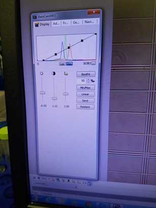
For customized camera color and light exposure adjustments, click the clipboard icon on the far right of the bottom toolbar on the software display. A new options menu with several tabs will appear.

Adjusting the bars on the "Display" tab will immediately generate visible changes to the live image screen. Selecting "restore" button on the first settings tab, "Display", will reset all camera settings automatically.
On the second tab, "Adjust", sliding the tone slider to warmer or cooler changes the color hue of the image and may make the organisms easier to identify. Images presented in this protocol have Ostreococcus appearing as a black/green nucleus on an orange hued background with white hemacytometer grid lines. To recreate this color scheme, move the slider to "warmer".

Additional desired image adjustments can be made in the properties menu. For additional image options, please refer to the AxioVision manual provided in the Materials tab.
Image Capture
Capture a time-point image from the live image feed using either the "Snap" button with a camera icon in the second from the top toolbar or using the camera icon "acquisition" button in the bottom toolbar of the software.

Multiple static time-point images can be captured or static time-point images can be captured after moving the hemacytometer. They will appear as sequential numerated snapshot tabs on the display behind the live image display.

Click on the desired snapshot to perform image analysis in the software such as scaling, angle measurement, or freehand drawing. Image analysis can not be performed on live image. Additional information about post-processing image analysis can be found in the AxioVision manual.

Click on the desired snapshot and then highlight the "Save As" disc icon in the second from the top toolbar in the software to save the individual snapshot as an individual photo file.

The individual photo files are now able to be transferred to other analysis software such as ImageJ with Cell Counter Add-In for enumeration.
