USER MANUAL of U-uF-BM# Bifurcating Mixing Microfluidic Chips
Serhat S
Abstract
This is the user manual for U-uF-BM# Bifurcating Mixing Microfluidic Chips of uFluidic.com.
It is designed to make nanoencapsulation liposomes and polimeric nanoparticles.
Steps
INTRODUCTION
THIS IS A BIFURCATING MIXING MICRO-CHANNEL. MAINLY DESIGNED FOR LIPOSOME AND NANO-PARTICLE GENERATION AND DRUG-VACCINE ENCAPSULATION PURPOSES.
DESCRIPTION
By laminar flow microfluidic channels, it is mostly accepted that these two were very hard;
- rapid mixing of liquids
- high volume fabrication
The BM5 microfluidic mixer is designed specifically for nanotech encapsulation of active pharmaceutical ingredients (API) and active food ingredients (AFI). Other classic serpentine or herringbone channel mixers have disadvantages about
- reproducibility at parallel devices
- high volume at scale-up
The NehirBT'S BM5 chip design is uniquely capable of high-throughput formulation synthesis of nanomaterials.
The BM5 bifurcating mixing channels enable the reproducible manufacturing of nanoencapsulation formulations at both researches to preclinical scales.
- Test batches of up to 1-2 L/h produced with a single chip
- Particle characteristics (size and PDI) are constant
- Biological activity maintained
- The nanoparticles suitable to be synthesized using BM5
- DBAB/Cholesterol Liposome
- Lecithin Liposomes
- PolyCaproLactone nanoparticle
- PolyCycloDextrine nanoparticle
- Solvent-Antisolvent reaction microparticle
- Chitosan nanoparticle
- Hyaluronic acid nanoparticle
ABOUT COMPANY
WE'RE A DESIGN AND FABRICATION CENTER FOR MICROFLUIDIC LAB-ON-A-CHIP DEVICES.
00903123860423
skype: live-ufluidic
Uzaycagi Cd. 1308 Sk. No:6 / B11
Yenimahalle, Ankara, Turkey
PC-06370

NECESSARY EQUIPMENT and CONSUMABLES
For pumping liquids inside microfluidic channels, we suggest the use of either pressure pumps or syringe pumps in your setup. Below you can find descriptions for both options. You are free to choose one of the pumping options, syringe or pressure control, and flow rate capacities may change accordingly.
Make ready enough syringe and syringe pumps for your number of liquids to be used.
If you have 3 liquid samples for example you need either one of the below options for syringe pump properties.
- Single syringe pump with 3 syringe capacity of pumping independent flow rates
- Three syringe pumps with a single syringe capacity of pumping different flow rates
Equipment
| Value | Label |
|---|---|
| SuP: micro Syringe Pump | NAME |
| Syringe Pump | TYPE |
| NBT | BRAND |
| NBT# | SKU |
| www.nehirbt.com.tr | LINK |
| 5 mL/min flow rate with 10mL syringe | |
| 15 mL/min flow rate with 20mL syringe | SPECIFICATIONS |
Make ready a pressure control pump for your liquid samples. Generally, one pressure control unit is required per liquid sample to be sent inside the chip. Equipment
| Value | Label |
|---|---|
| FlowEZ | NAME |
| Pressure control pump | TYPE |
| Fluigent | BRAND |
| FlowEZ | SKU |
| http://www.fluigent.com | LINK |
| 2-7 bar pressure source | |
| 1 mbar control resolution | SPECIFICATIONS |
Inverted, stereo or digital microscope to visualize the devices, microchannels and inner sample.
-
Inverted microscopes are suggested for their high magnification capacity and most of the biology laboratories already have them.
-
Stereo microscopes are suggested for their large working area and large visualization area.
-
Digital microscopes are suggested for being cheap and mobile.
-
Trinocular and high-speed camera integrated ones are preferred.
-
Most of the microfluidic channels are around 100 um in size so 10x-20x magnification is enough.
-
When the channel dimensions are larger than 300 um, then stereo and digital microscopes with low magnification are suggested.
-
When the channel dimensions are smaller than 50 um in size then higher than 20x magnification is suggested.
Equipment
| Value | Label |
|---|---|
| Görcell: Smart Microscope | NAME |
| Microscope | TYPE |
| NBT | BRAND |
| NBT#Görcell | SKU |
These are required consumables for any kind of microfluidic chip from NehirBT or uFluidic.com during the experimental study.
-
Syringes with Luer or Luer-lock tips to hold samples during pumping if you use syringe pumps (at least 10mL volume)
-
15 mL - 50 mL tubes with an equal number of samples if you use pressure control pumps.
-
Tubing to connect the syringes or pressure control units to chips (silicone or any flexible material with suitable ID and OD dimensions is suggested)
-
Fittings of "syringe-to-tubing" and "tubing-to-chi"p to complete liquid flow path through chip if you use syringe pumps (NBT original fittings at uFluidic.com are suggested)
-
Cell strainers and filters to filter out any dirt, contamination or agglomerations inside sample liquids Suggested: 25um or 40um cell strainer filter
These may be required liquid samples specifically for experimental studies with BM# microfluidic chips.
-
Nanoparticle monomers; dissolved in distilled water, alcohol, or organic solvent.
-
Lipid and cholesterol monomers; dissolved in alcohol or organic solvent.
-
Nanoparticle cross-liked chemicals in suitable solution
-
Molecule of API or AFI to be encapsulated; dissolved in water or suitable solvent.
-
Pure distilled water
-
Ethyl alcohol of %70 for sterilisation and cleaning
QUICK START GUIDE
A. SET UP the FLUIDIC SYSTEM.
-
Put the chip on a microscope or stage and make stabilized.
-
Connect the tubings and fittings with the pumping instrument.
B. ARRANGE the suitable liquid FLOW RATE and PUMP the liquids.
-
Send the nanoparticle monomer or lipid solution first to fill the micro-channels.
-
Send all the required samples at suitable pressure or flow rate.
DESCRIPTION of DEVICES
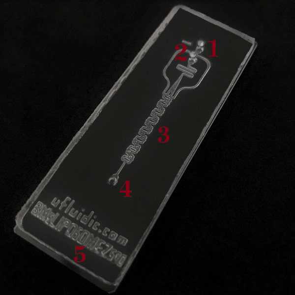
A single chip contains a single device of microchannels. BM# chips have multiple inlet options lease refer to the chip code and find the correct inlet number.
-
Inlet port at outer location for BM5.
-
Inlet port at inner location for BM5.
-
Mixing channel region.
-
Outler port for BM5.
-
Here the code of the chip is given.
Table-1: The properties of BM# series serpentine mixing microfluidic chips.
| A | B |
|---|---|
| Specification for BM5 chips | Info |
| Number of Devices per Chip | 1 device |
| Total Length of Microchannels After Mixing Point | 2 cm |
| Material | PDMS bonded on microscopy glass |
| Bonding Technique | Oxygen plasma treatment |
| XY Size of Total Chip | 25x73 mm2 of the chip on 26x76 mm2 of std microscopy glass |
| X Width and Z Height of Microchannels | 500 um |
| Z Height of PDMS Chip | 3.0 - 4.0 mm |
| Ports on Top/Edge | on Top |
| Number of Ports | 2 inlet ports and 1 outlet port per device |
| Size / Shape of Ports | Variants available / circle |
| Micro Channel Geometry | rectangular |
EXPERIMENTAL PROTOCOL
Open the package and
- Take care of the chips.
- Remove the protection tape on top of the chips
- Be sure it is in good condition and there is not any breakage
Prepare fittings, tubing, and chemicals
- Enough number of syringes and "syringe-to-tubing" fittings per liquid sample when you use syringe pumps.
- Enough number of tubes and pressure cap fittings per liquid sample when you use the pressure pumps.
- Enough amount of tubing with correct dimensions.
- Enough amount of "tubing-to-chip" fittings for inlets and outlets.
- Open reservoir fitting can be used for collection at the outlet.
- Plug fitting is not suggested to be used anywhere during this setup.
Fill the syringes with suitable liquids
- Fill one of the syringes with sterile distilled water when you use syringe pumps.
- Fill the syringes with your samples per device, 5 mL minimum, when you use syringe pumps.
- Fill one of the tubes with sterile distilled water when you use the pressure pump.
- Fill the tubes with your samples per device, 5 mL minimum, when you use pressure pumps.
- Do not leave any bubbles inside the syringes and tubing after filling.
Connect syringes and tubes with tubing and fittings
- Fill the liquid inside the connected liquid pathway of tubings.
- Do not leave any air bubbles inside the liquid pathway.
Connect inlets with sample liquid tubing
- Connect liquid pathway tubings to the chip by the inlet ports.
- Connect the water phase molecule solution to the inlet outer inlet port.
- Connect the encapsulant nanoparticle or lipid monomer phase solution to the inner inlet port.
- Beware of any air bubbles.
- Check if there is any leakage in the liquid pathway.
Outlets
- Outlets can stay free for initial adjustments.
- Beware of any air bubbles.
- Check if there is any leakage in the liquid pathway.
Pumping velocity
- It is suggested to apply a minimum 3 mL/min flow rate for the water phase molecule solution to obtain successful results.
- It is suggested to apply a lower flow rate for encapsulant nanoparticle or lipid monomer phase solution to obtain successful results.
- Higher flow rates may be needed for your sample materials to optimize target nanoparticle size and encapsulation ratio.
- Higher difference between water and encapsulator phases' flow rates to optimize the target nanoparticle size and encapsulation ratio.
- Very high flow rates may cause high pressure to break the bond between PDMS and glass.
NO Closure on the outlets
- Do not close or plug any outlets which will disrupt the mixing and chemical reaction of the samples.
- Use any suitable tubing to chip fitting for equal pressure effect on-chip.
Which outlet?
- Observe the product liquid sample through outlets and find the outlets to be used for collection.
- Connect fittings with tubing to the outlets for product liquid collection.
NO Closure on the inlets
- Never close the inlet ports. The system does not work in a backwards direction.
Stable flow
- Wait for 30 seconds to obtain stable flow and stable diffusion mixing or experimental product.
- Fine-tune the flow rates for desired mixing efficiency regarding product properties.
Collecting product in a tube
- Connect a tubing and a fitting of tubing-to-chip on the correct outlet ports.
- Place the other end of the tubing inside a suitable tube of 0.5 mL – 50 mL.
TROUBLESHOOTING
Problem-1: Flow is not present
Solution:
It takes time to push liquid samples in syringes, tubing and press air in microchannels. You may need to wait longer to stabilise flow inside channels. Please also check the conditions below;
- Any leakage from fittings and or the microchannels disrupt the proper flow of liquids, please be sure there is not any leakage from syringes, pressure controllers, pressure source tubings, fittings, inlet ports, or inside microchannels.
- Any clogging in channels also disrupts the proper flow, please check if all the microchannels are open and free of debris.
- Ensure the syringe back is moving and the pump is working properly.
- Ensure the pressure source and pressure controllers are working properly.
- Air bubbles in any part of the microchannels or tubing may also disrupt the laminar flow and pressure stabilisation required for sorting. Please make sure there are not any air bubbles in the flow.
Problem-2: Flow is not stable under the same pressure
Solution:
In order to obtain stable, uniform, and laminar flow, whole the system must also be stable. Please check the conditions below;
- Tubings must stay stable and without vibration. The shorter the tubing the better the results.
- The vertical level of syringe pumps must be at an equal level or higher than the chip on a microscope or bench.
- The syringe pump or any other pumping actuator must be as low pulsation as possible. Higher the pulsation of the pump, lower the uniformity of droplets, or particles.
Problem-3: Particles or Cells are lost
Solution:
This is easy to solve a common problem in microfluidic experimentation. Please check the conditions below:
- Wetting the chips totally with sterile distilled water or PBS or nanoparticle monomer is necessary before starting the application. This makes the surface ready for your sample so no one sticks on the channel walls.
- Mix the tubes, tubings and syringes from time to time to solve the precipitation of particles or cells inside tubes, syringes or tubings.
Problem-4: Particles or Cells are not observable
Solution
Under optimum conditions flow rate is equal between pump and microchannels but the velocity of the flow is much higher inside channels due to the contraction effect. Please check the conditions below;
- Observe the wider channels just before outlet ports to see the particle or cell separation. The wider the channel, the slower the particles or cells.
- Use fluorescent beads with a similar diameter to your target particles or cells so tracking the fluorescence is easier.
- Label the target particles or cells with fluorescent dyes for initial optimisation so tracking the fluorescence is easier.
- Use a high-speed high fps camera with your microscope to be able to observe the sample ingredients.
Problem-5: Clogging of channels with particles or dirt
Solution:
- The width of microchannels is given in the user manual. Please filter all the liquid samples previous to the application by proper filters according to the width of microchannels. If clogging occurs, under some conditions, inverted flow by pressure through outlets may clean the clogging.
- Applying lower flow rates may cause larger microparticles than our target. So if there is clogging inside channels during particle synthesis, then increasing the total flow rate is a must to have smaller and faster particles.
Problem-6: For any other problems regarding the microfluidic chip capabilities and properties
Solution:
Please let us know by email or call via the contact details given above;
- For any problem, the microchannels can be cleaned with distilled sterile water or ethanol at some level. For other PDMS compatible or non-compatible materials, please check our blog pages.
- The amount of protein in water-based sample, also, strongly influences the droplets. For example, Serum is strongly inhibitory and must be washed out completely.
GLOSSARY
Lab-on-a-Chip: Highly integrated microfluidic system providing laboratory functions.
Microfluidics: The science of manipulating and controlling fluids, usually in the range of microliters (10^6) to picolitres (10^12), in networks of channels with dimensions from tens to hundreds of micrometres.
Microfluidic Subsystem: Fluidic systems may contain one or many MEMS components which are subsystems such as controlling, signalling, analysis, and/or modification elements, attached to a larger system or subsequent process.
Microfluidic Devices: Within each chip, the separate microchannels of microfluidic application with a minimum 1 inlet and connected outlet.
Biocompatibility: Refers to a special quality of some materials allowing them to come into contact with biological materials without changing the materials’ bioactivity.
Bifurcating Mixer: This is a type of microfluidic channel, squeezing and enlarging the channels to disable the laminar flow and mix the liquid samples quickly.
Droplet Microfluidics: The science of manipulating and controlling immiscible liquids to form droplets in the range of nanoliters.
Inside Reservoir: A wider microchannel area relative to other channels of the same microfluidic device to collect, analyse, or incubate specific droplets, cells, particles, or molecules.
Microreactor: A device in which chemical reactions take place in confinement with typical lateral and/or vertical dimensions below 1 mm.
Fittings Accessories: parts related to microfluidic chips to connect tubing to chips and syringes for flowing samples through.
Single Layer Droplets: This is a single cover or single capsule of droplets such as water-in-oil (w/o) or oil-in-water (o/w). For multi-layer droplets, multiple layers of phases are needed such as water-in-oil-in-water (w/o/w).
OD, ID: OD stands for outer diameter and ID stands for inner diameter.
REUSING and STORAGE
The PDMS microfluidic chips on glass can be stored for up to 24 months without removing the coverage and without direct sunlight exposure and high humidity at room temperature.
15Room temperature
The used chips can be reused if
-
cleaned with ethyl alcohol correctly
-
visual inspection done to see all channels are stable
-
covered again with 3M Magic tape and put inside a plastic tube.
Safety informationThe bottom of the microfluidic chips are made by microscopy glass. So in the case of breaking of glass, protect your hands.
