ROBOFISH construction
Lars E. Borm
liquid handling
microfluidics
imaging
microscopy
FISH
smFISH
spatial transcriptomics
spatial
pump
valve
temperature control
flow cell
EEL
EEL FISH
sequencing
Abstract
The ROBOFISH system is designed to do liquid handling, temperature control and imaging. We use it for cyclic RNA detection with Fluorescent in situ Hybridization but it can be used/adapted to perform any experiment that requires these 3 components.
This guide contains all steps to build this machine and operate it.
Steps
System overview
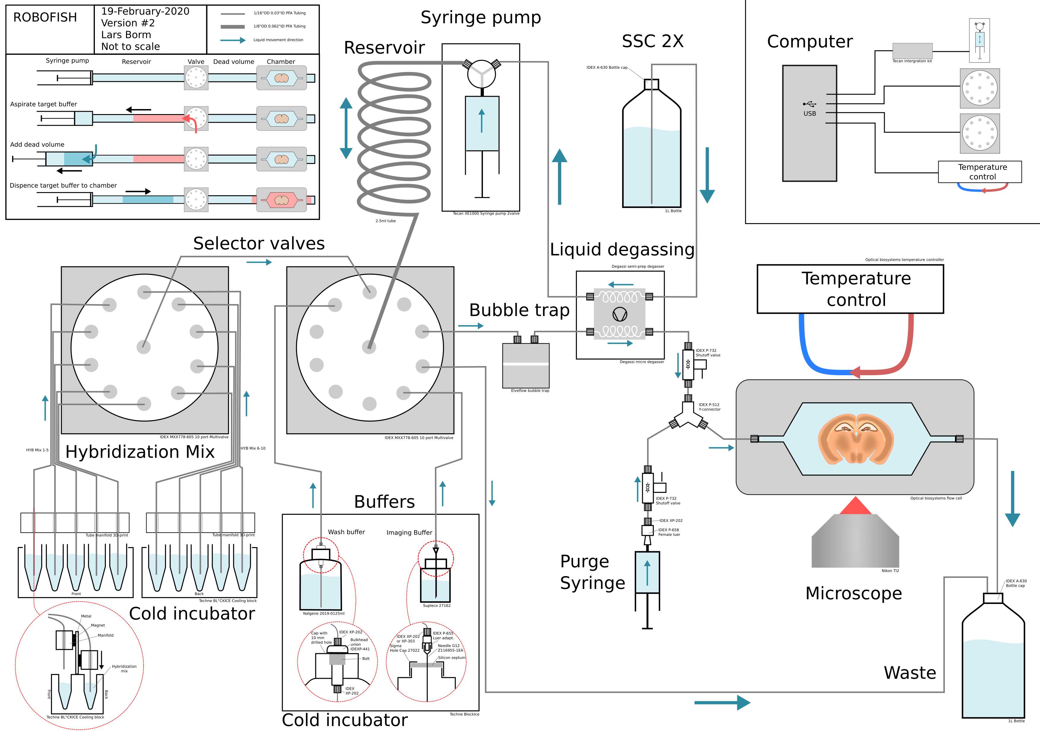
Please download this schematic overview of the system: Schematic_ROBOFISH.pdf
All parts of the fluidic system are included and labeled with part numbers.
The system can dispense arbitrary small volumes to the flow cell that contains the sample. In the top left corner the working of the system is visually explained.
-
The system consists of a syringe pump that is connected to a multi-valve through a 2.5ml reservoir made out of a big tube. The volume of the reservoir matches the volume of the syringe pump. The buffers and the flow cell are all connected to the multi-valve.
-
To dispense a target buffer, the multi-valve connects the buffer to the pump and reservoir. Then the syringe pump aspirates the desired volume (red arrow and red volume). The target buffer volume now sits in the front end of the reservoir.
-
Between the multi-valve and the tissue in the flow cell, there is a dead volume that needs to be bridged. This is caused by the volume in the connecting tubes, the bubble trap and the degasser. To bridge this volume the syringe pump aspirates the same volume of Running-buffer buffer (SSC 2X in the case of smFISH), that is directly connected to the syringe pump, directly into the syringe (blue arrow and dark blue volume).
-
To dispense the target buffer to the flow cell the multi-valve now connects the syringe pump with the flow cell. Then the full contents of the syringe pump, made of the volume of the target buffer and the dead volume, are dispensed so that the target travels over the dead volume and into the flow cell.
The system can dispense arbitrary volumes by aspirating them into the reservoir and then use its own Running buffer supply to bridge the dead volume. In systems where buffers are pulled towards the flow cell this is not possible because small volumes will inevitably cause air to be sucked up through the tubes. In this pushing system, aspirated air can simply be expelled by pushing it to the waste port.
The system can work with two different flow cells; either the FCS2 from Bioptechs or the flow cell of Rebus Bio (contact Rebus to ask if it is commercially available). Towards the end of this document you will find the steps to install either one of them. The flow cells require a different way of heating. For the FCS2 temperature control a recirculating heater/cooler is required and the ROBOFISH code is compatible with the Solid State Cooling Oasis with this Python library or the Solid State Cooling ThermoCube with this Python library. The code for the Oasis unit was made for an older model but will probably work for newer models as well. For the Rebus Bio flow cell this python library is needed for the control. All these Python libraries are supported by the ROBOFISH code.
We advise to power all the machines of the fluidic system, microscope and computer using an Uninterrupted Power Supply (UPS) like the APC Smart-UPS 2200 To prevent loss of the experiment due to power failure.
The system is operated by a number of Python scripts which can be found here:
https://github.com/linnarsson-lab/ROBOFISH
There you will also find detailed installation and set up instructions.
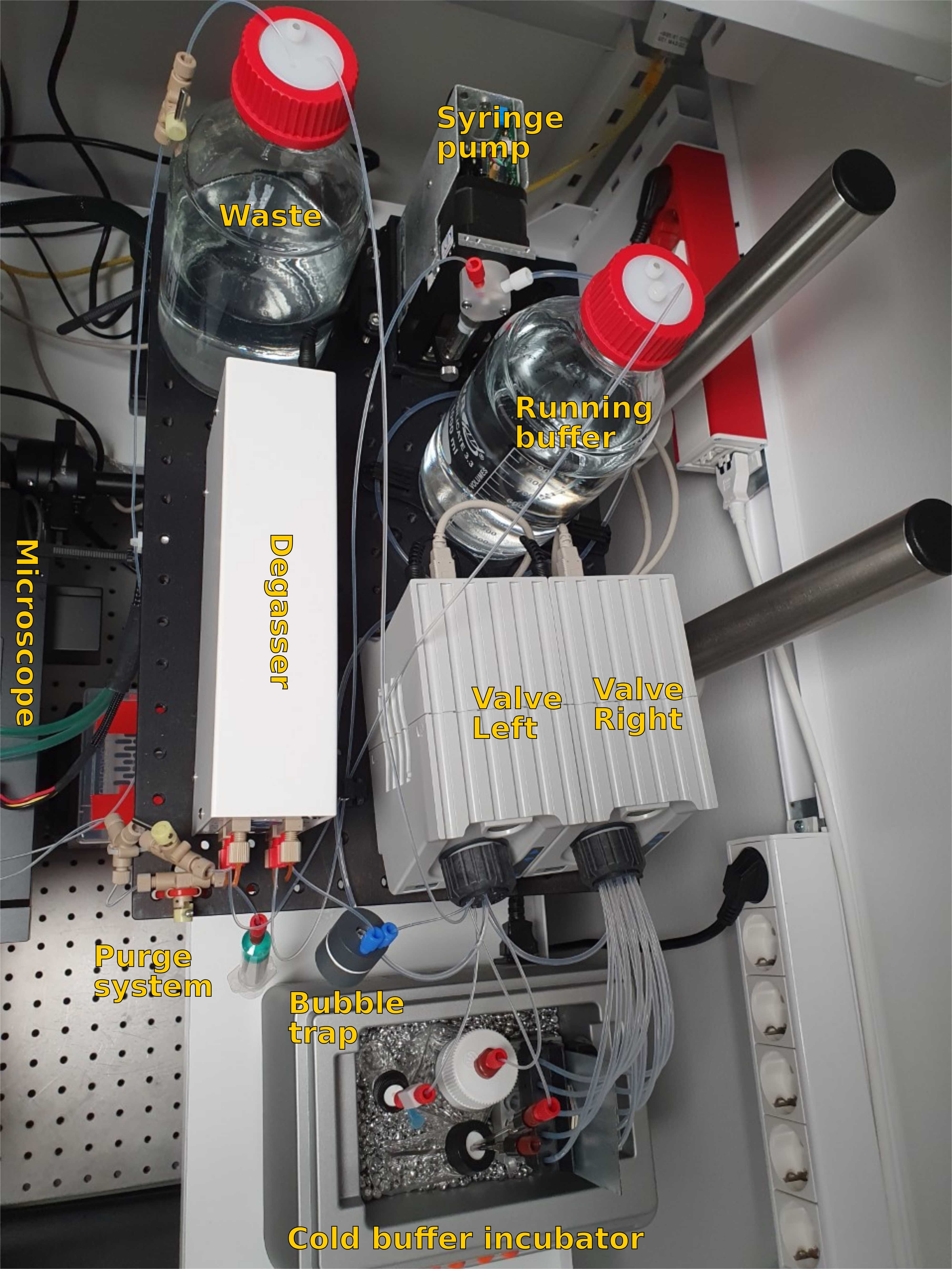
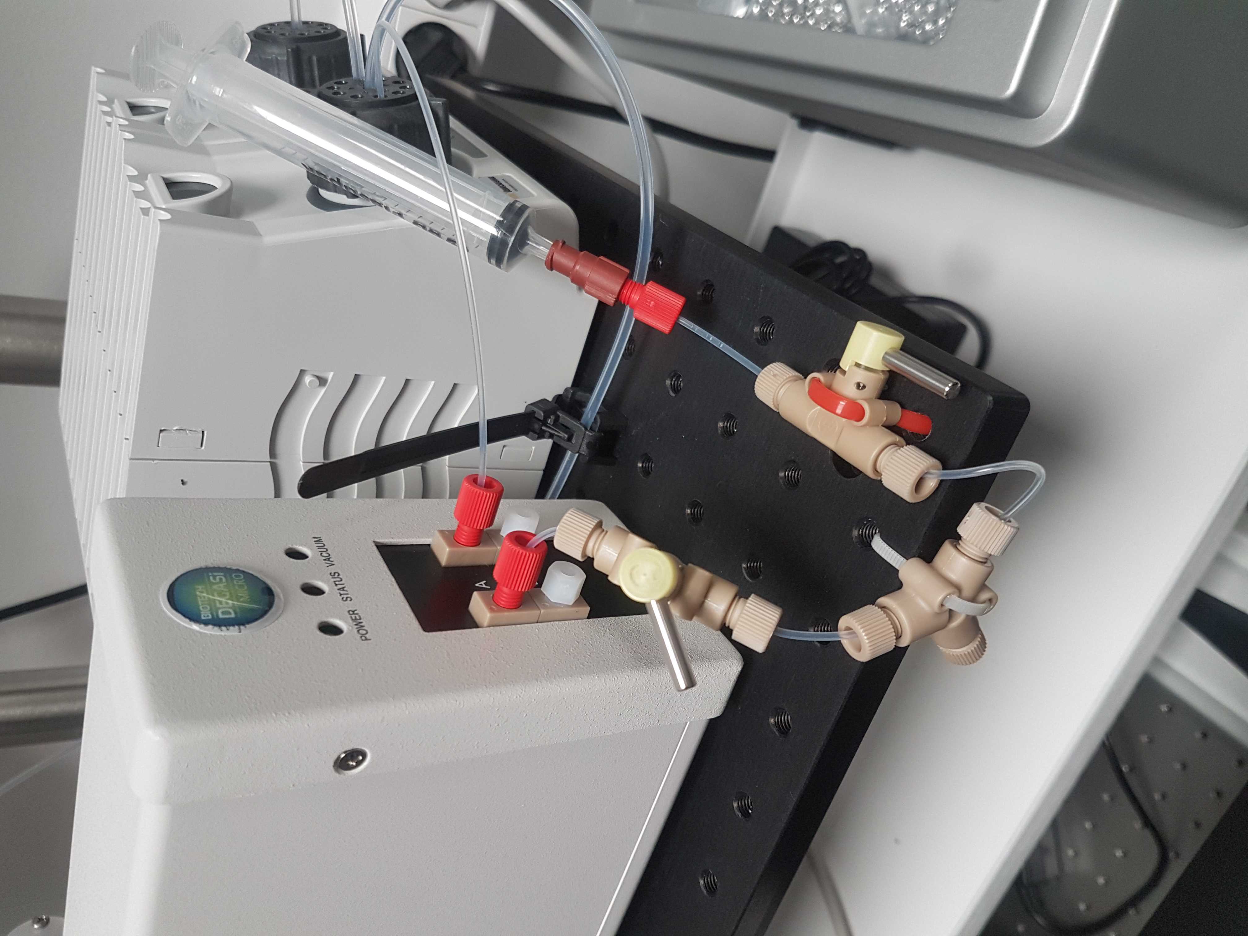
Top view of finished system
Support
Building platform
Make two building platforms to construct the system on. Make sure it is close to the microscope stage.
This manual assumes that the microscope is to the left of the fluidic system. However, the system can easily be mirrored.
Here we use a regular shelf mounted on the wall and a Thorlabs MB3045/M Aluminum Breadboard of 300 X 450mm with M6 screw taps, mounted with two Thorlabs PSY321 Post-Mounted breadboard brackets, on the microscope table (Thorlabs SDH7590 with B7590L). The shelf can be replaced with another breadboard mounted on the same posts.
Cold incubator
Place the Techne BlocIce on the bottom surface and adjust the hight of the breadboard to be 50mm higher.
Depending on the climate and humidity the cold incubator can collect condensation so it might be good to seal the seams and screws with silicon glue to protect the electronics.

Assemble fluidics
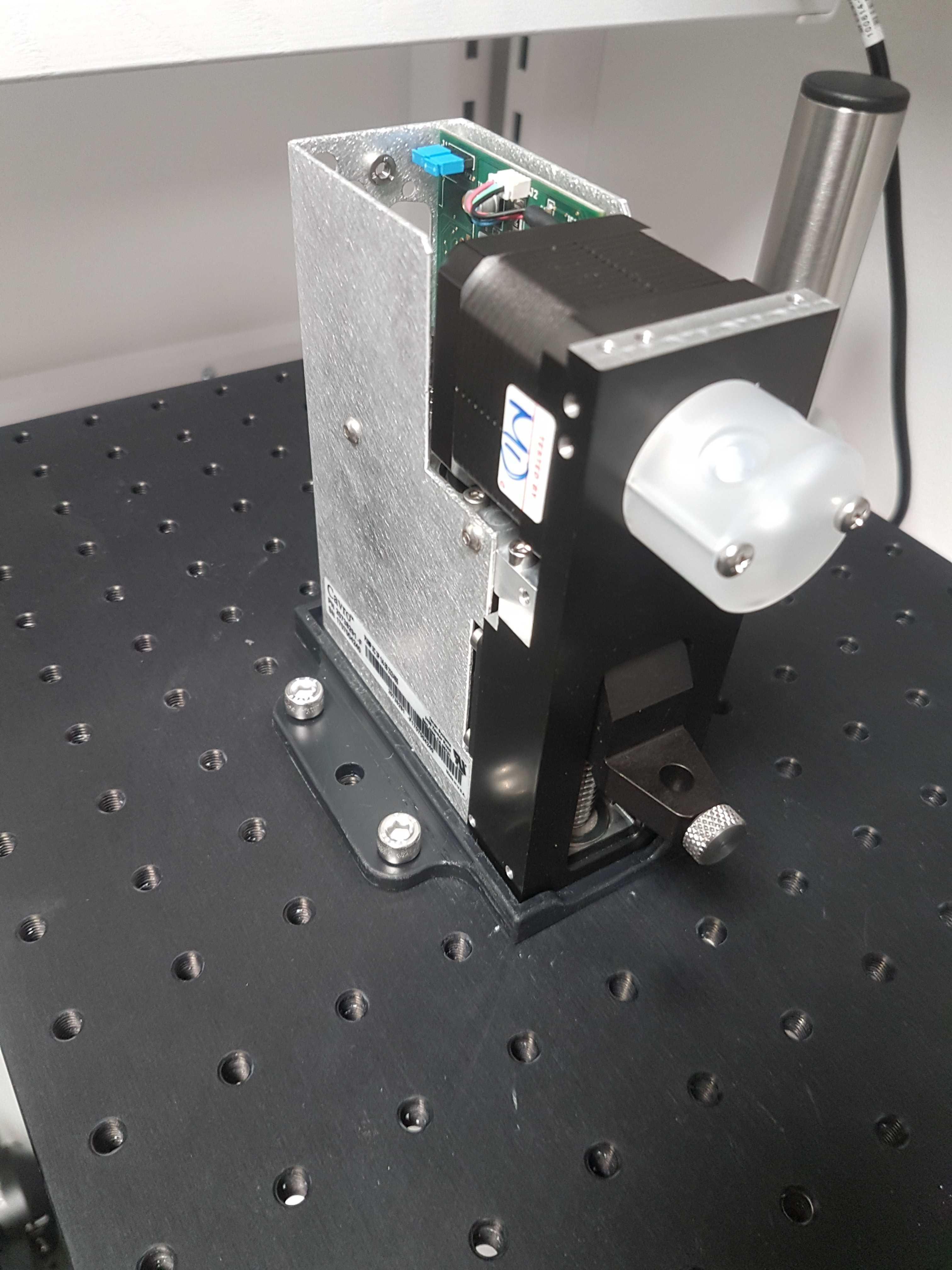
Mount syringe pump
Using a 3D printed base for the syringe pump available here. Mount the Tecan Cavro XCalibur syringe pump on the breadboard with M6 bolts.
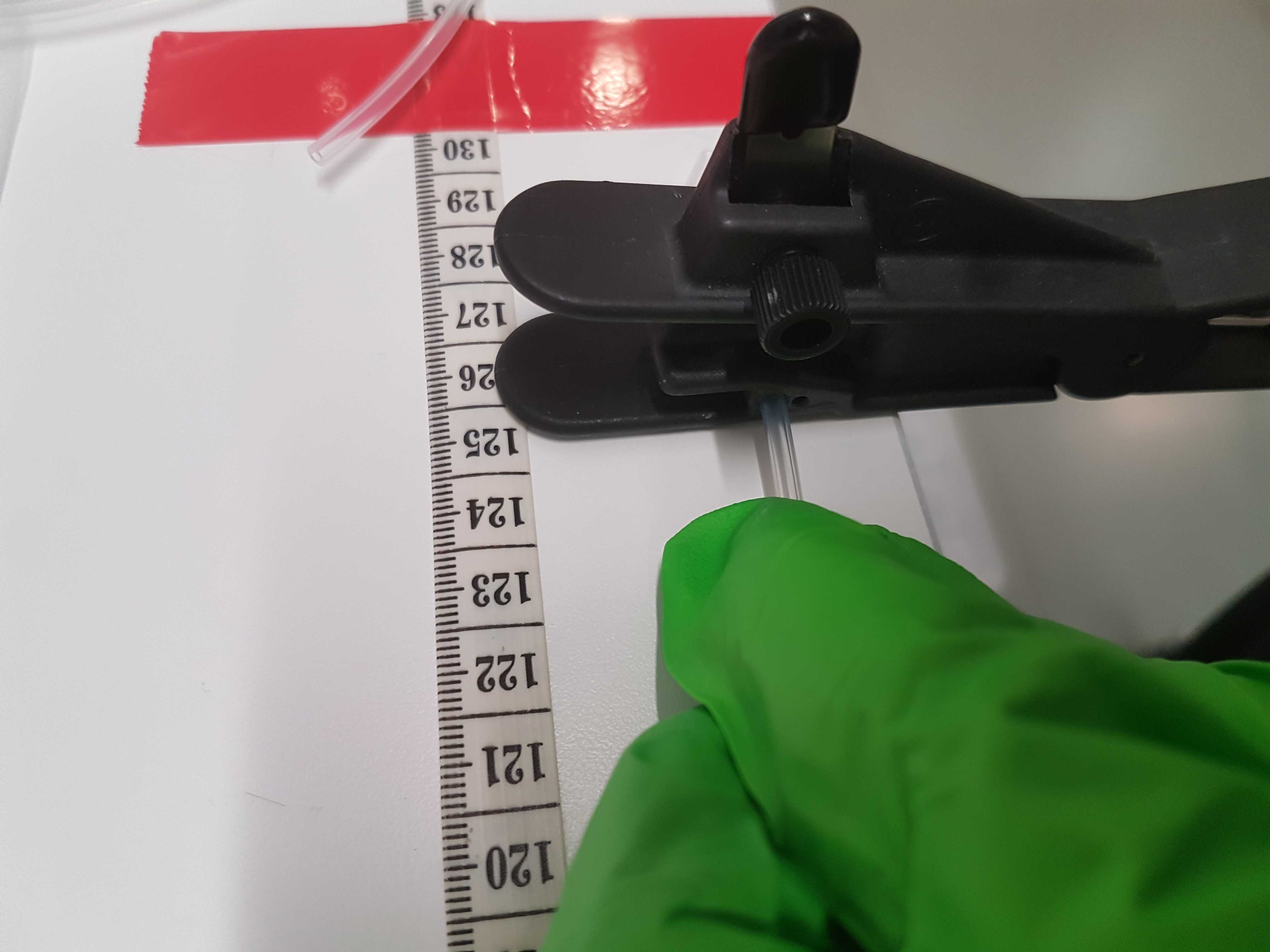
Make the 2.5ml reservoir
Calculate the length in cm of the tube using:
For IDEX XP-3030 tubing with 1/8 inch Outer Diameter (OD) and 1/16 inch Inner Diameter (ID), the length should be 126.3cm
Using measuring tape and a plastic tubing cutter tool IDEX A-327, cut the tube to length.
Connect reservoir
Mount the reservoir to the right port of the syringe pump with an IDEX XP-303 1/8 inch Delrin nut and ferrule.
Mount reservoir
Use the empty tubing case to mount the reservoir to the breadboard with an M6 bolt.

Install left valve
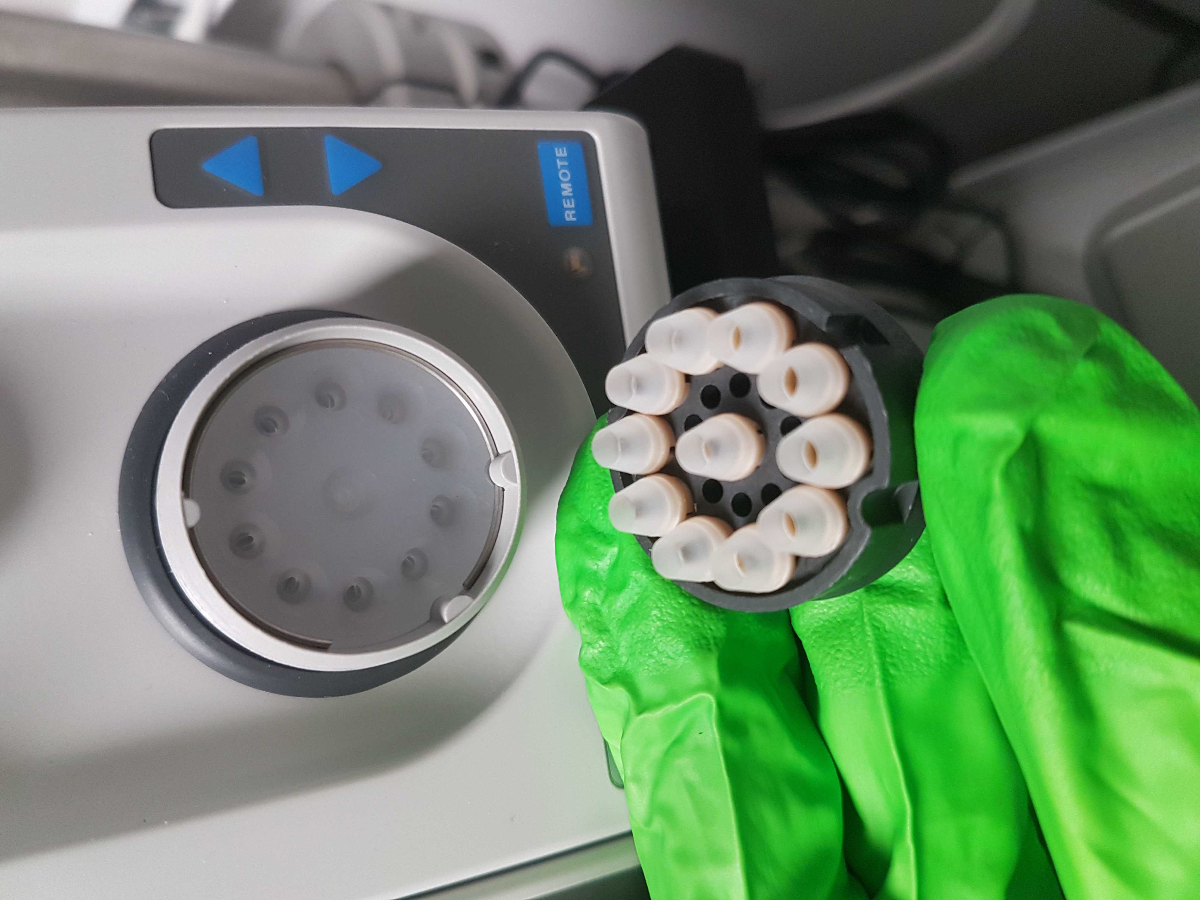
Position the two IDEX MXX778-605 selector valves on the breadboard.
Open up the ring of the left valve and make sure there are 1/8 inch connectors in positions: Center, 7, 8, 9 & 10. The rest should have 1/16 inch connectors. (Make sure to remove the green o-rings of the 1/16 inch connectors before inserting the 1/8 inch connectors)


Install right valve
In the right valve, place 1/8 inch connectors in all ports.
Close the ring loosely.
Tube connection instructions
In the next steps you will connect the tubing of the reservoir, buffers, waste and output to the valve. To do this make sure the tubing is cut properly so that the end is flat. We recommend using a special tube cutter for this, IDEX A-327. Push it in the hole of the valve and make sure it goes all the way to the back. For the 1/16 OD inch tubing, you should feel the tube passing the green O-ring. This takes quite some force and you will know once you are passed the O-ring. If you are not sure, you did not pass it yet. When pressing the tube in, hold it with your fingers 5-10 mm from the valve and make sure you do not fold the tube when applying force.
When all tubes are installed, close the ring slightly more, and press all tube to make sure they are fully inserted. Repeat this process if necessary.
Now, tighten completely. The valve ring needs to be very tight to prevent leakage, especially if a mix of tubing outer diameters is used, so don't be afraid to put a lot of force into it. Keep an eye on leakage the first time it is used.
Connect reservoir
Insert the reservoir tube in the center of the left valve. Press all the way down.
Connect left valve with right valve
With a 15cm piece of 1/8 inch tubing connect the left valve (suggestion: port 9) to the center of the right valve.
Connect degasser
(see step 15 before starting)
Place the degasser on the breadboard to the left of the valves.
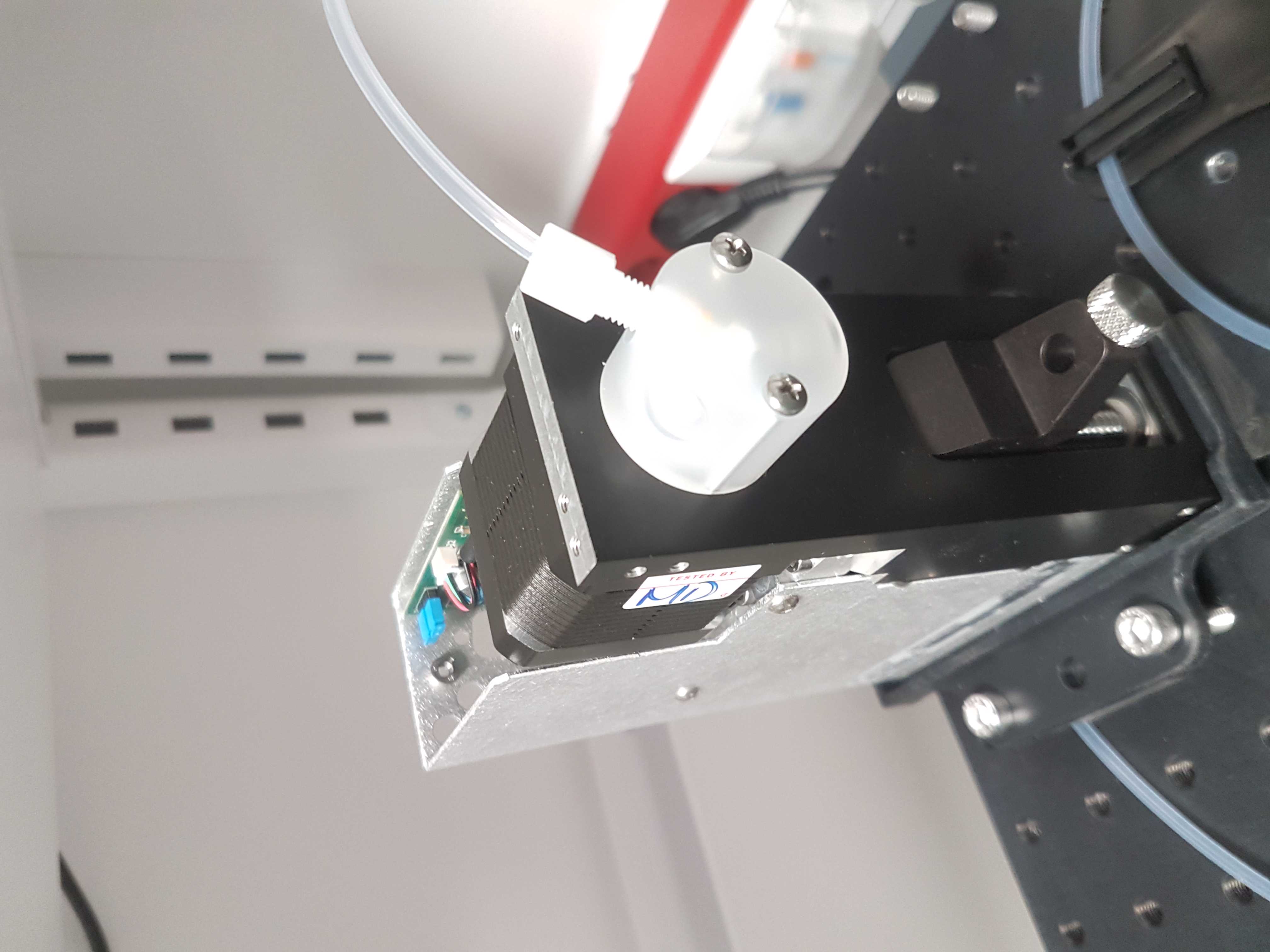
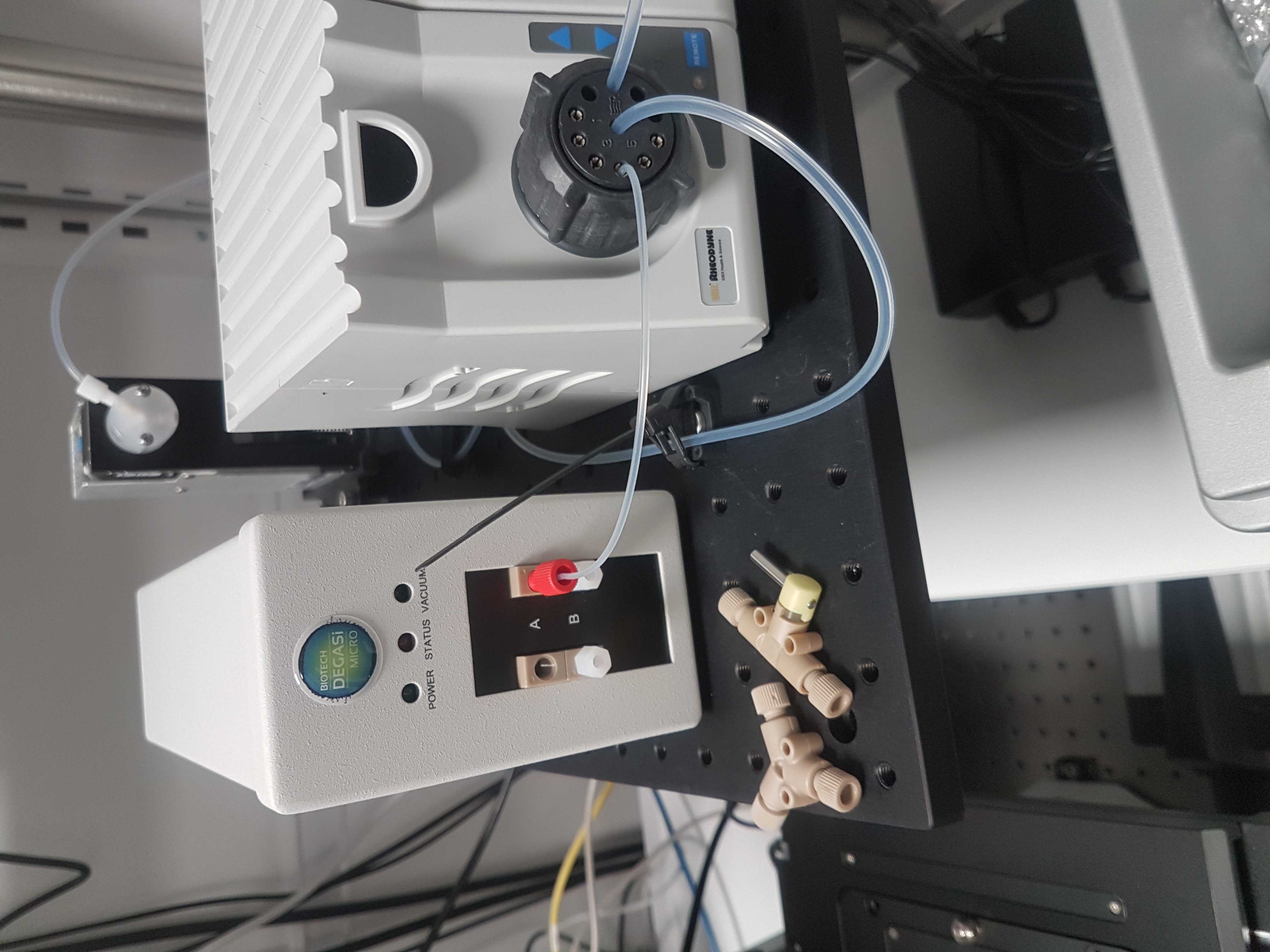
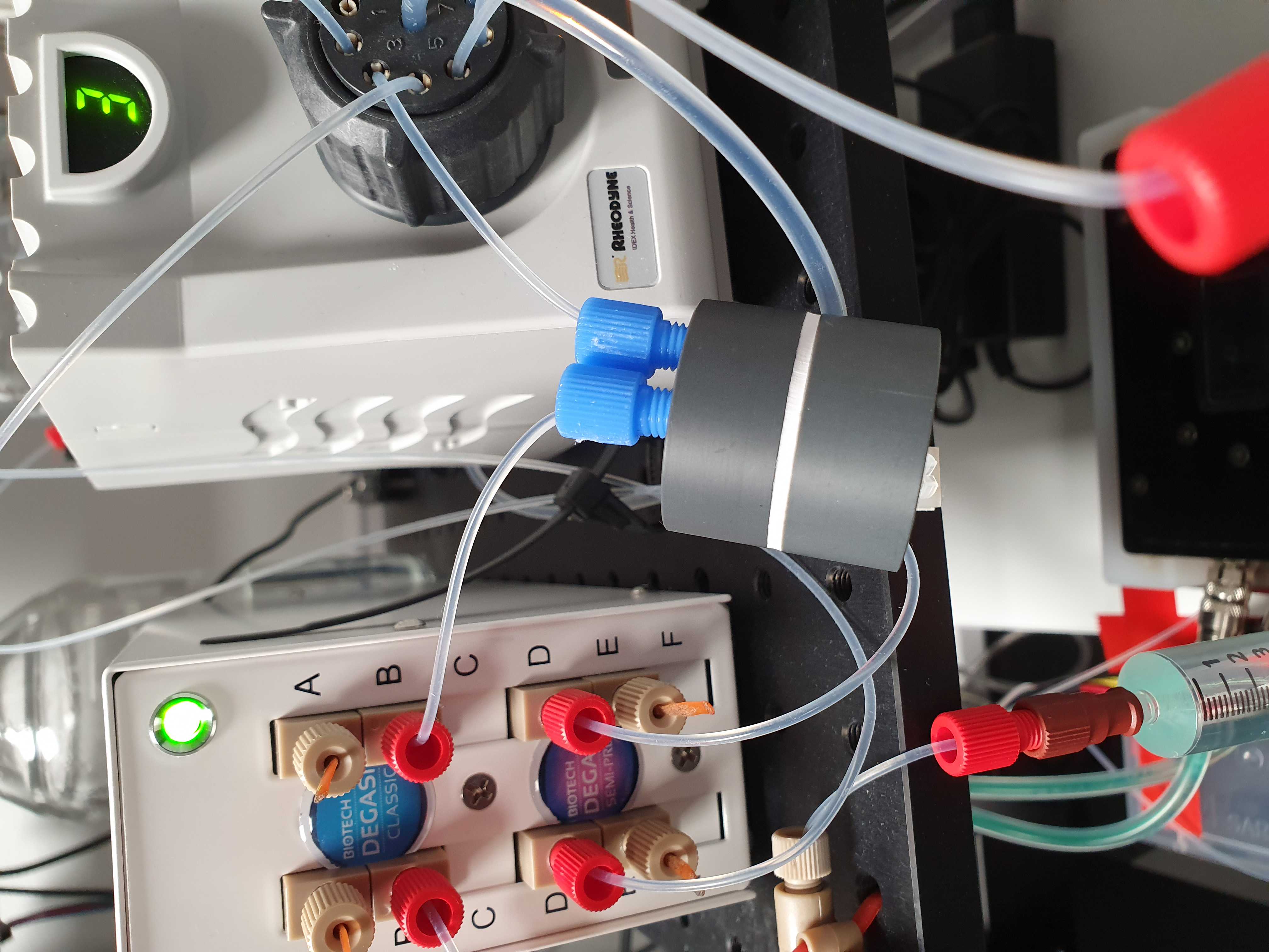
Press a 20 cm piece of IDEX 1514L 1/16 inch outer diameter PFA tubing into one of the ports of the multi valve. You should feel when the tube passes the O-ring inside. Use an IDEX XP202 flangeless fitting and ferrule, to connect the other end of the tube to the Biotech AB Degassi Classic degasser. (The pictures contain the Degassi Micro but the internal volume proved to be small to degas properly at the used flow speeds.)
Connect debubler
Alternatively you can add an Elvenflow bubble trap between the valve and the degasser with two pieces of 5cm tubing and the provided blue fittings.
Connect shut-off valve
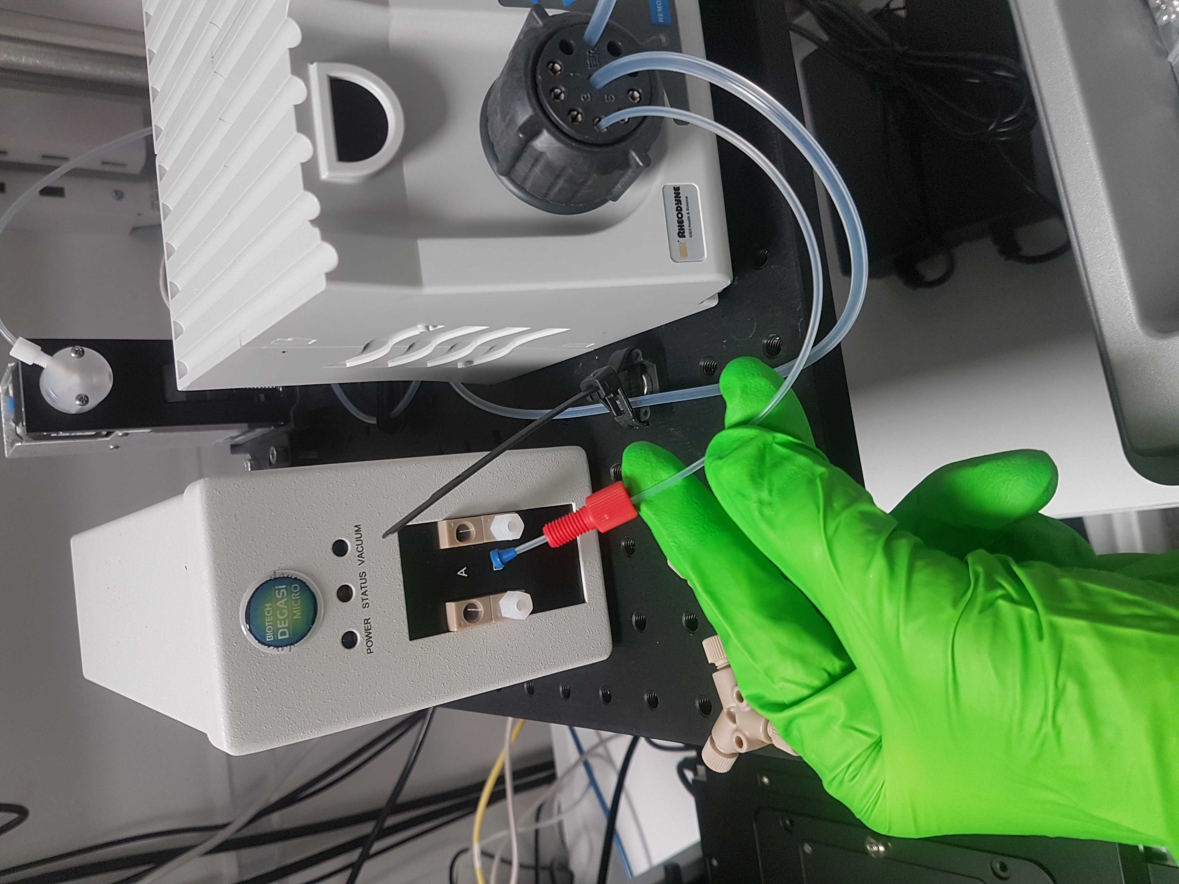
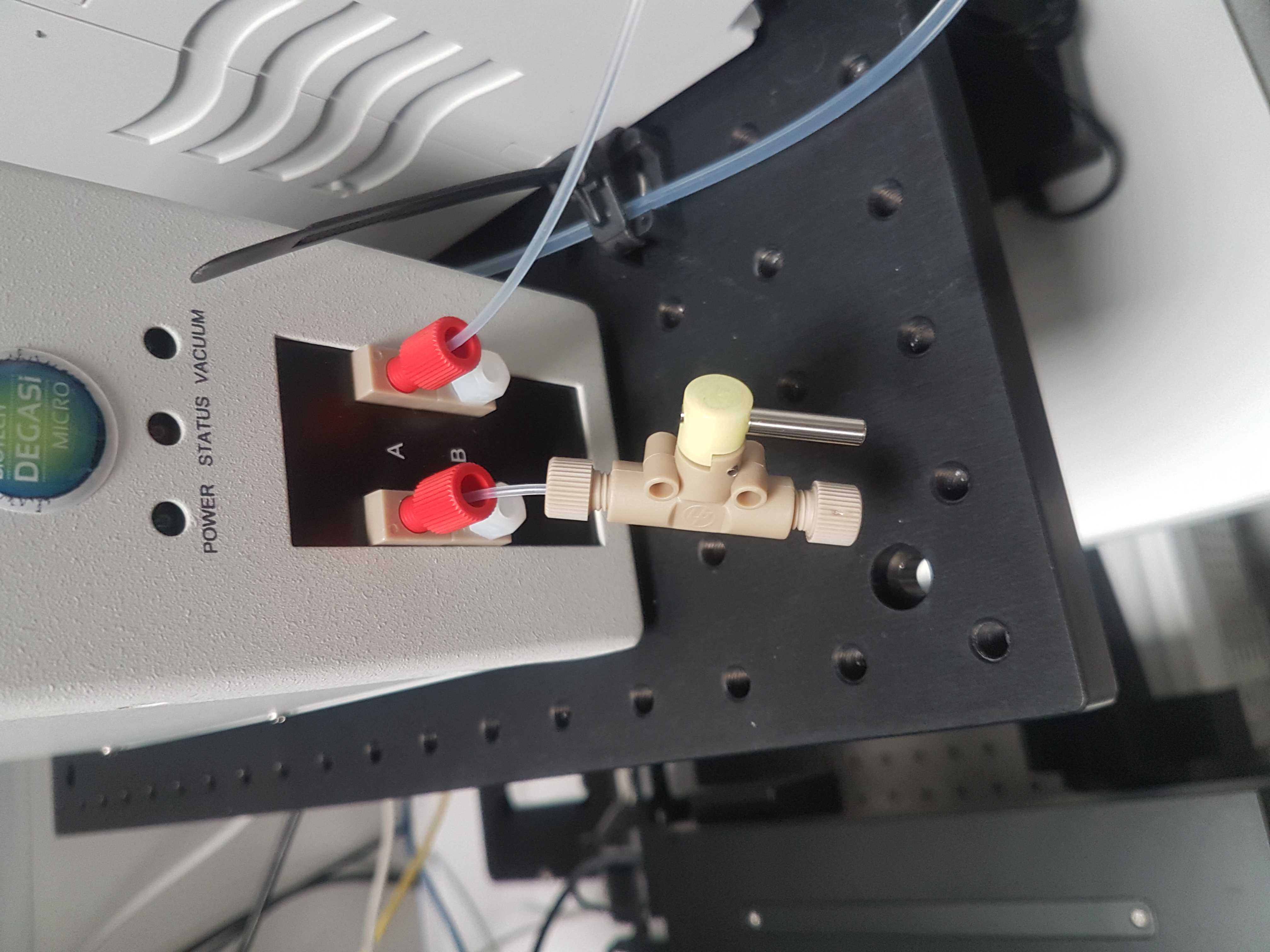
Connect the other port of the degasser with a 5cm piece of IDEX 1514L and a XP202 fitting and ferrule, to an IDEX P-732 manual shut-off valve.
Connect purge system
Using 5cm of IDEX 1514L tubing, connect the shut-off valve to a IDEX P-512 Y-connector.
To the other arm, connect another shut-off valve with 7 cm of tubing.
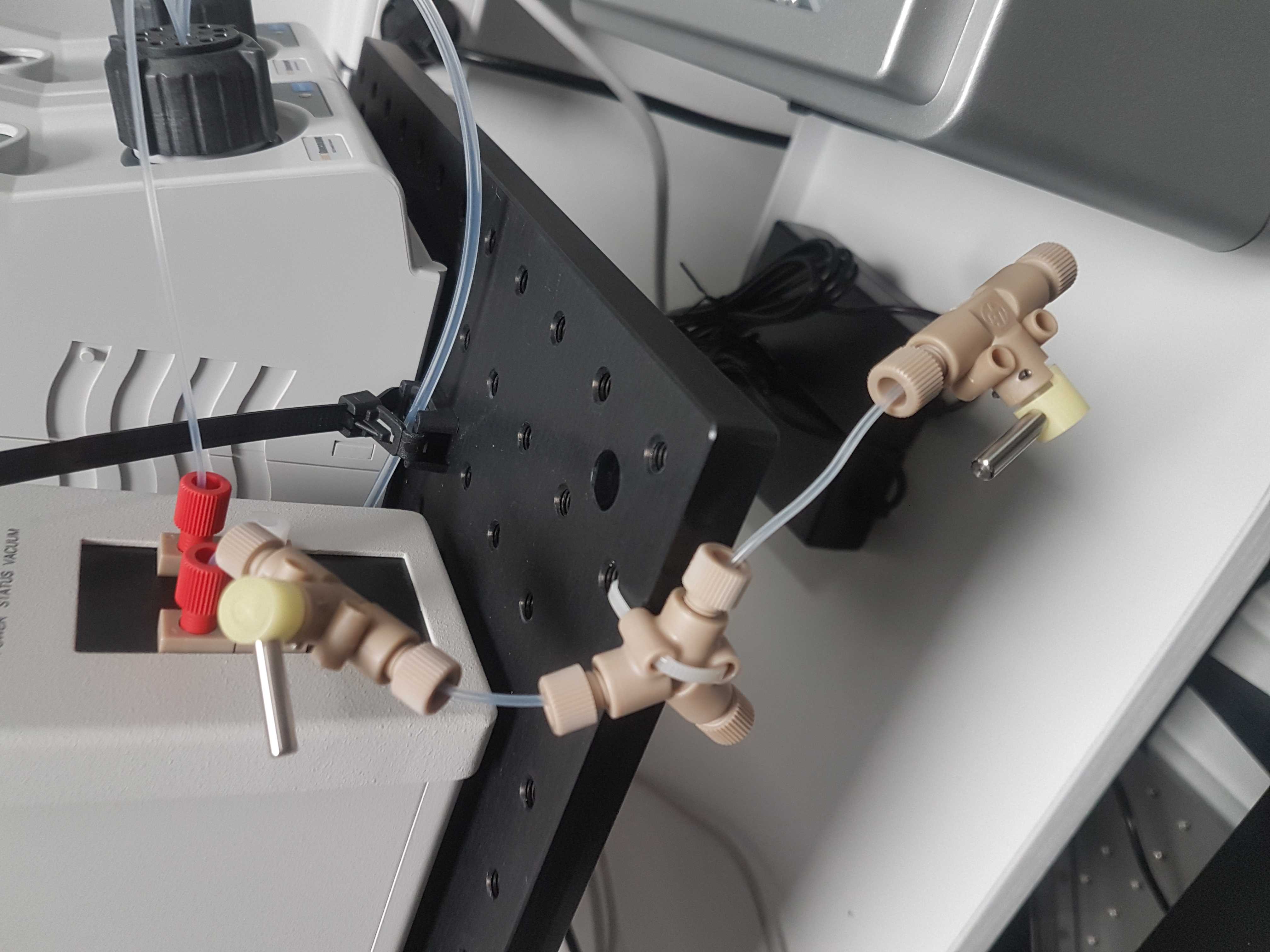
Mount syringe connector
To the free shut-off valve connect an IDEX P-678 (or P-696) female luer adapter with an XP-202 fitting and ferrule and 7cm of tubing.
Alternatively use an IDEX P-696 female luer adapter that contains a valve which seals the system when no syringe is present.
This part of the system can be used to manually purge the flow cell with a syringe to expel air bubbles.
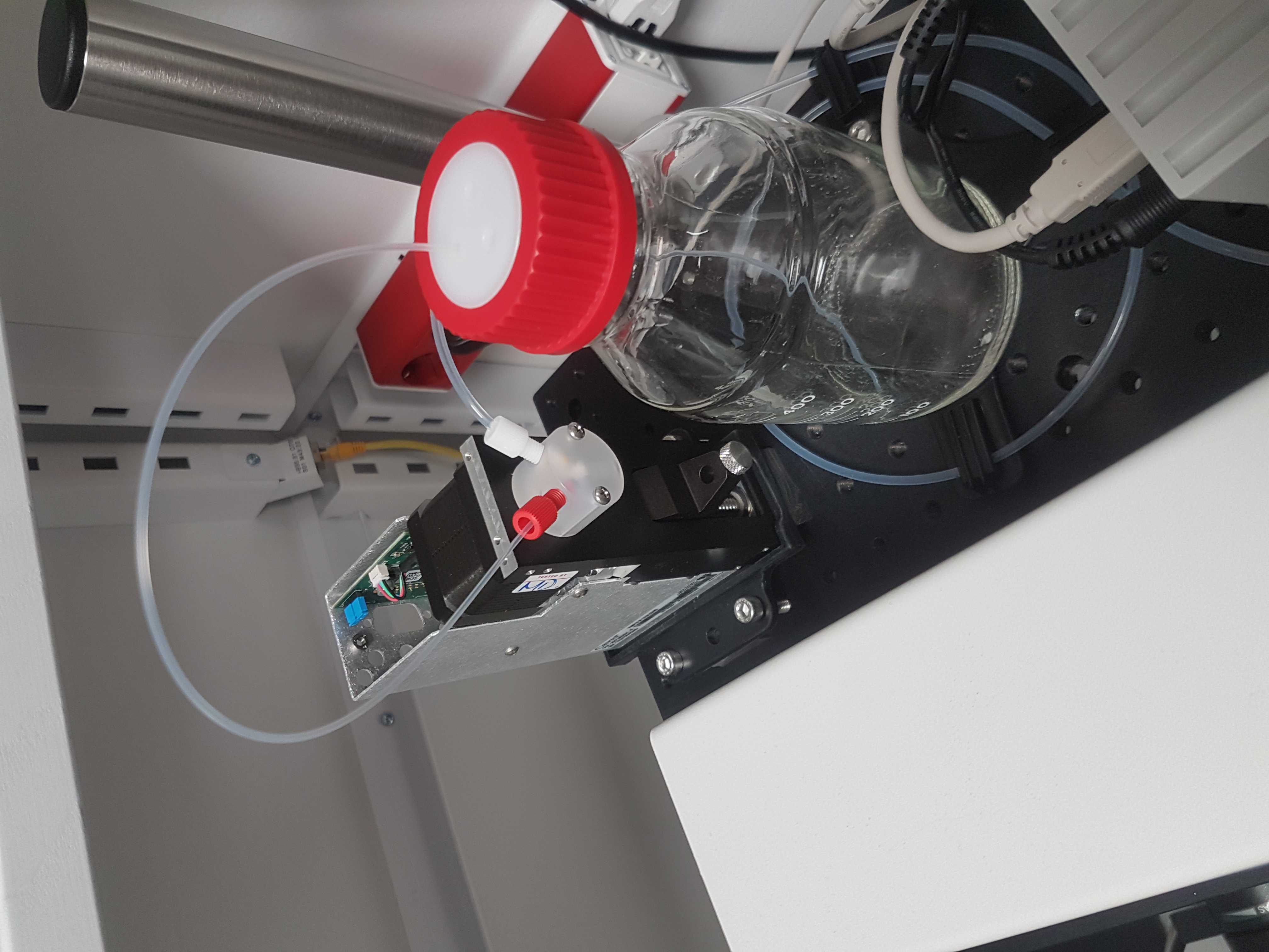
Connect the running buffer bottle.
On a 1 liter glass bottle mount an IDEX bottle cap A-630, close two of the holes with an IDEX A-627 filtered plug and an IDEX A-628 plug.
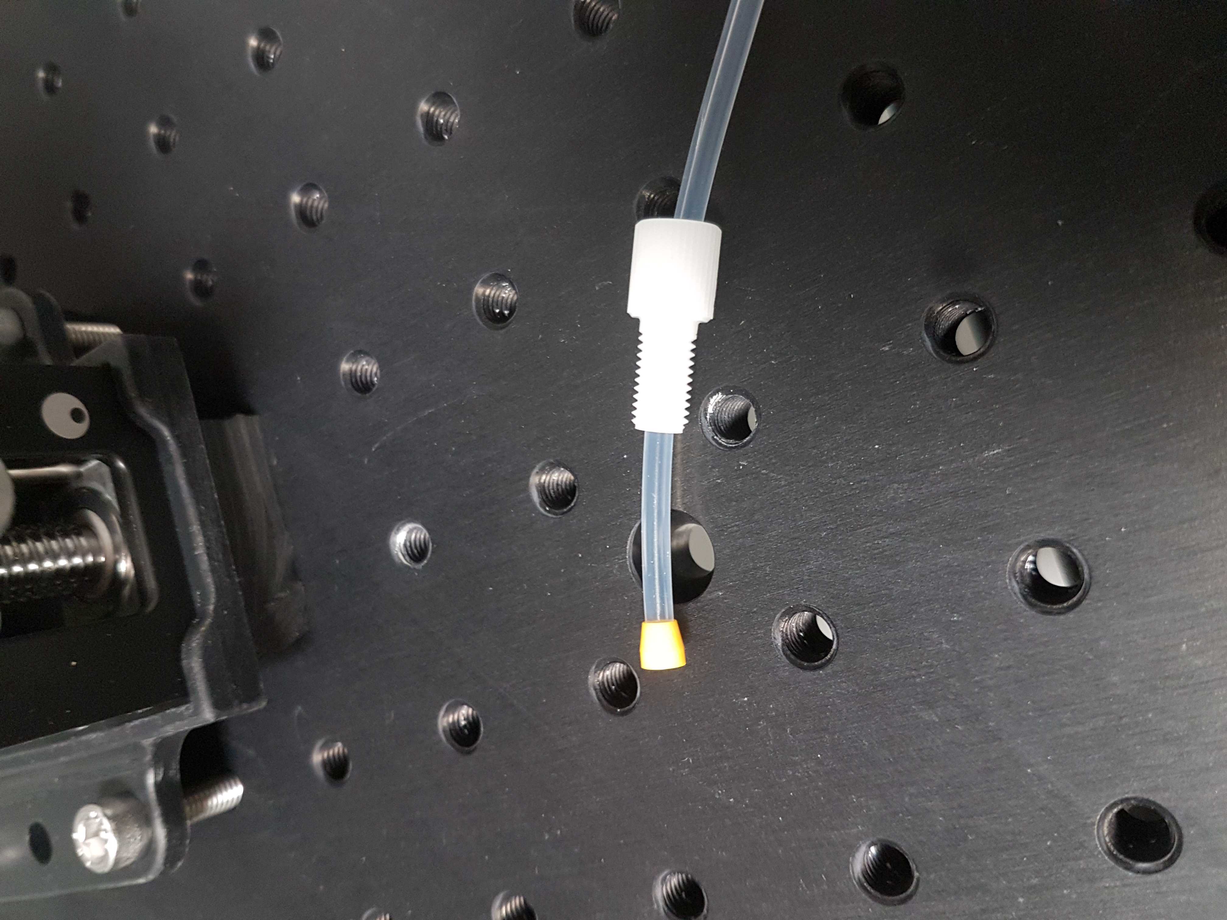
Take 45 cm of 1/16 inch OD tubing and taper one end. Pass it through the open hole of the bottle cap and lower it so that the tapered end touches the bottom. The taper will make sure that the tube can not pull a vacuum on the surface of the bottle.
Mount the other end to the left port of the syringe pump with and XP-202 fitting and ferrule.
Alternatively, run the tube from the bottle first through a free port of the degasser and then connect to the syringe pump. This will ensure that liquid is free of dissolved gas before entering the system. For this we have a hybrid degasser where a Degassi Classic is used for the main fluid line and a Degassi semi-prep for the running buffer. (not included in all pictures)

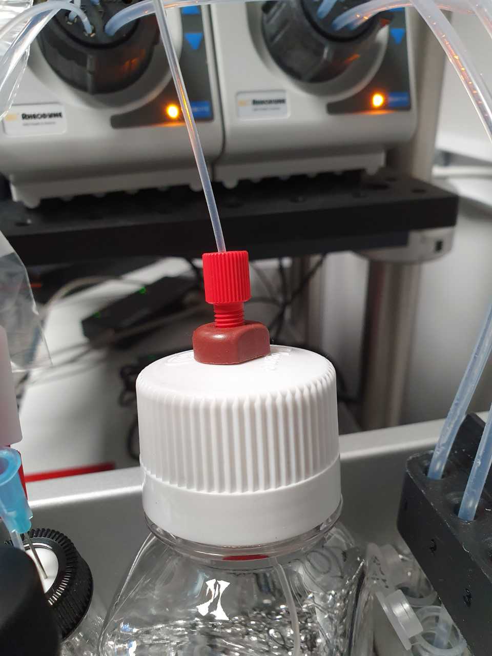
Large buffer container
Drill a 1cm diameter hole in the cap of a Nalgene style 2019 250ml bottle. Mount an IDEX P-441 bulkhead union through the hole. Place the bottle in the cold incubator and cut 1/16 inch OD tubing to length so that it can connect the left valve to the bottle. Use a XP-202 fitting and ferrule to connect the tube to the bulkhead union.
On the inside of the bottle, cut a piece of tubing so that it reaches the bottom. Taper the end and use an XP-202 fitting and ferrule to connect it to the bulkhead union.
Connect as many as needed to the left valve. For the EEL protocol you need one for the washing buffer.
Medium buffer container (40ml)
Connect an IDEX P-655 male luer connector to a Sigma Z116955-1EA gauge 12 non-coring needle. Stick this through a Supelco Supleco 27022 septum cap on a Supelco SU860001 glass vial. Run an appropriate length of tubing from the valve to the luer adapter and connect with an XP-202 fitting and ferrule.
When using the system place a small needle through the septum so that the vial does not pull a vacuum when liquid is removed.
Connect as many as needed to the valve. For the EEL protocol you need one for the stripping buffer.
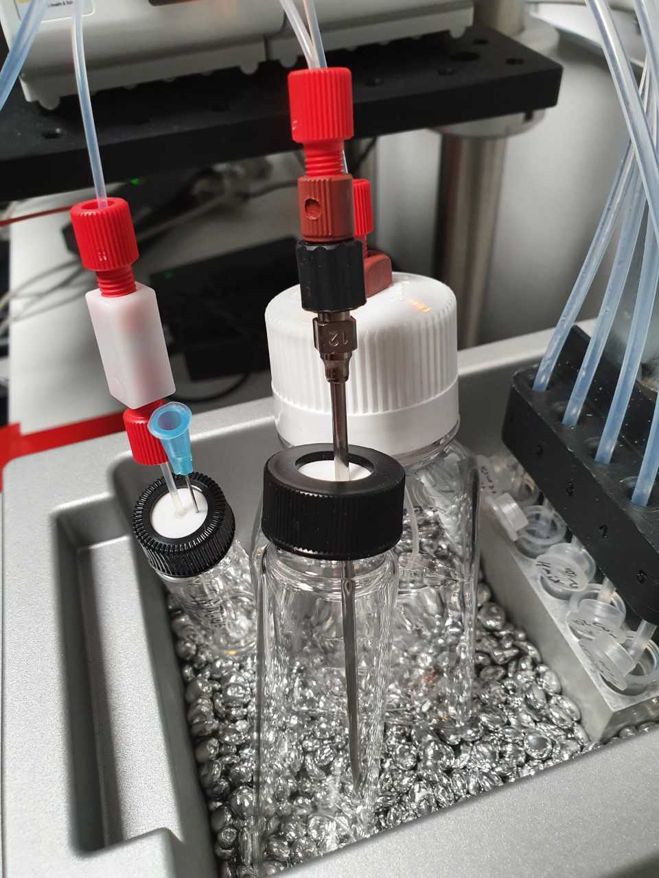
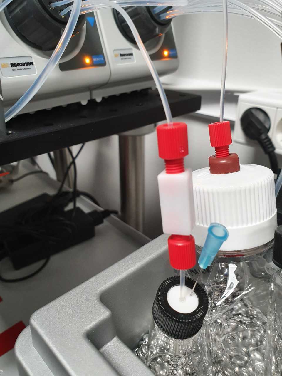
Small buffer container (15ml)
Pierce a hole through the rubber of a Supelco 27020 septum cap on a Supelco 27162 15ml glass vial. Run a tube of appropriate length from the valve to the bottom of the vial. Taper cut the end of the tube. Optionally, place an IDEX P-603 union in the tube for easy replacement of the part of the tube that is in contact with the buffer.
When using the system place a small needle through the septum so that the vial does not pull a vacuum when liquid is removed.
Connect as many as needed to the valve. For the EEL protocol you need one for the imaging buffer.
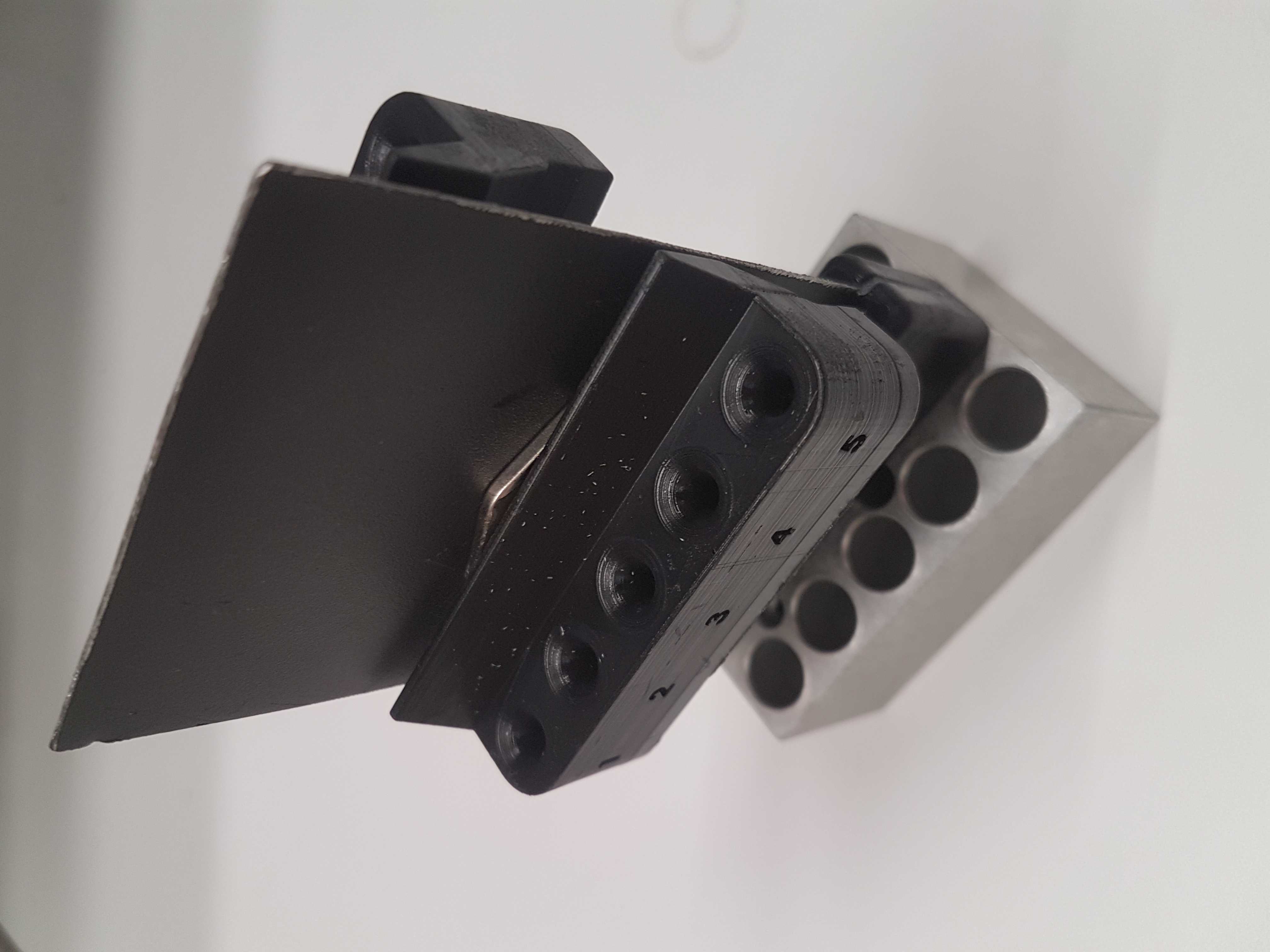
1.5ml tube connector
The right valve connects to 10 1.5ml Eppendorf tubes. The Eppendorf tubes are placed in a metal block to keep them cold, and a sliding mechanism can lower the tubing into them.
Start by 3D printing the metal plate adapter Metal_sheet_cooling_block_adapter.STL and the two tubing holders Hyb_mix_manifold_1-8-tubbing_1,5Tubes_cold-block_1-5.STL Hyb_mix_manifold_1-8-tubbing_1,5Tubes_cold-block_6-10.STL.
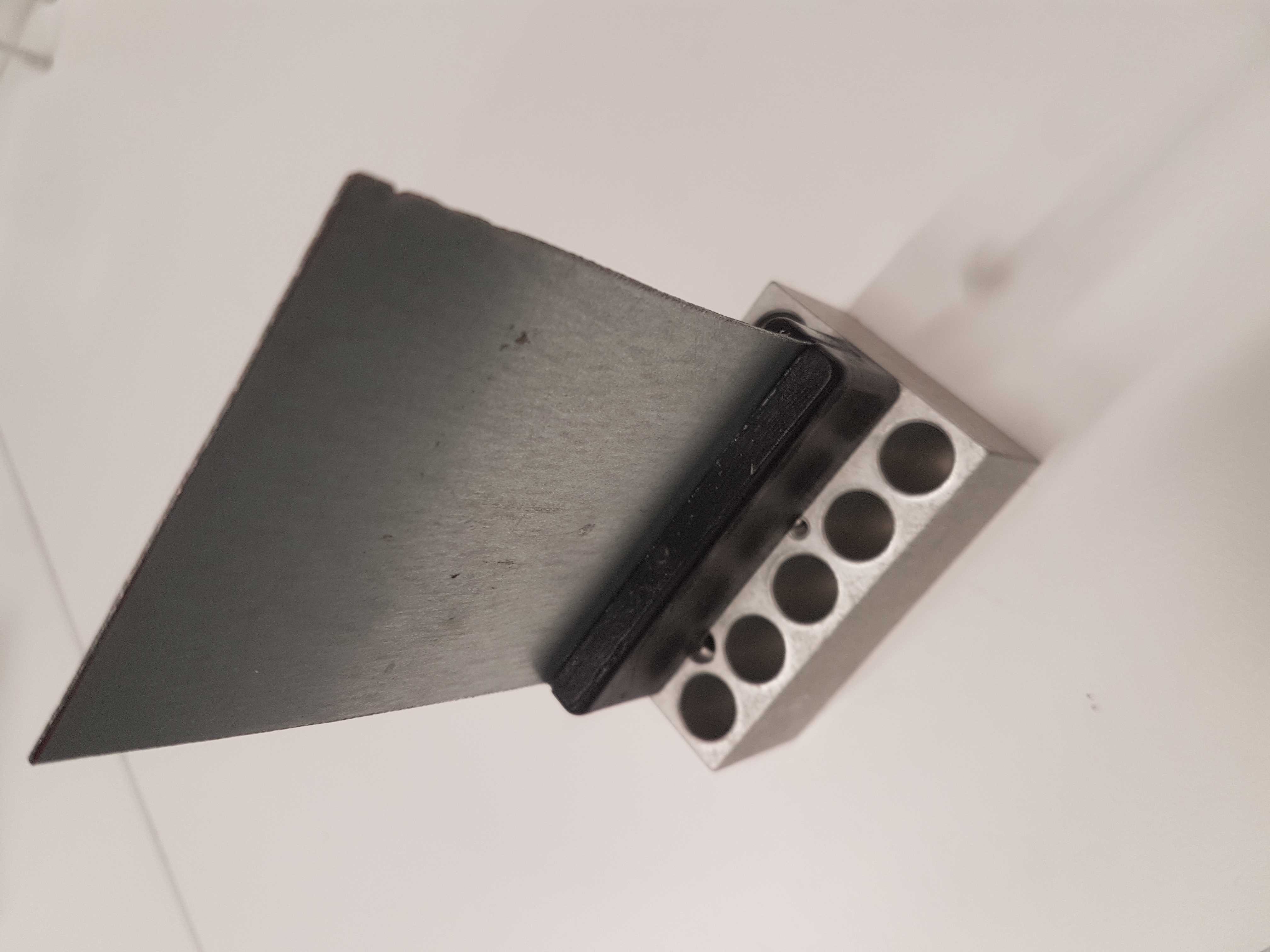
The full part is shown below and the next steps will cover the assembly process.
Metal plate
Push the metal plate adapter into the middle row of a VWR 460-0340 3x5 1.5ml tube block. Take a 7x10cm ferrous metal plate of 1mm thick and glue it into the slit of the metal plate adapter. The metal was sourced from an old desktop computer case.
Magnet tubing holders
Take two strong magnets, about 2mm thick and glue (Loctite) these to the back of the tubing holders. The magnets were sourced from an old hard disk drive.
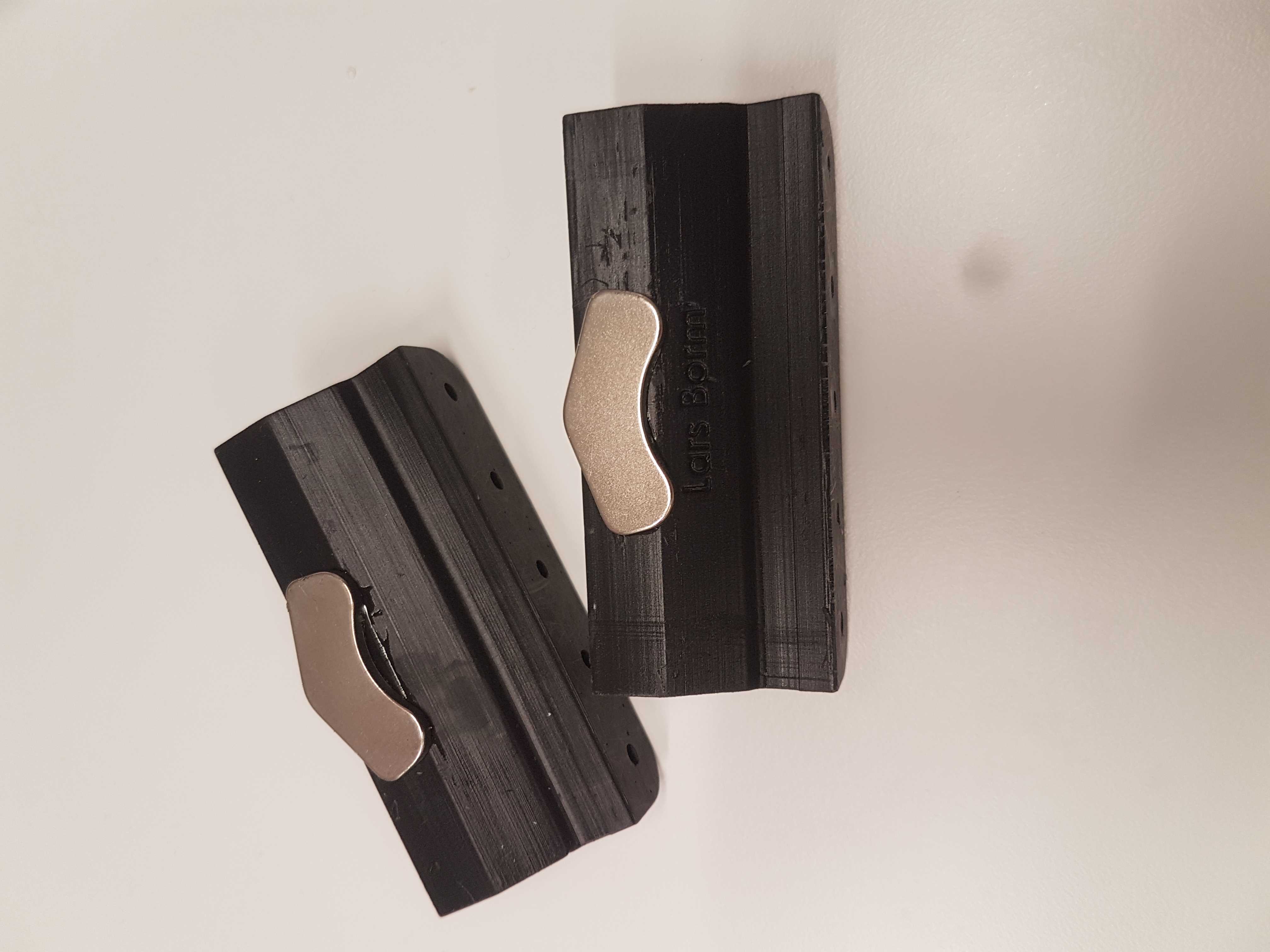
Assembly
When dry, assemble the part by latching on the tubing holders to the metal plate. The metal block can be fixed in place in the Techne BlocIce with thermal conductive double sided tape (Like Elfa Distrelec TCT35) or any other double sided tape.
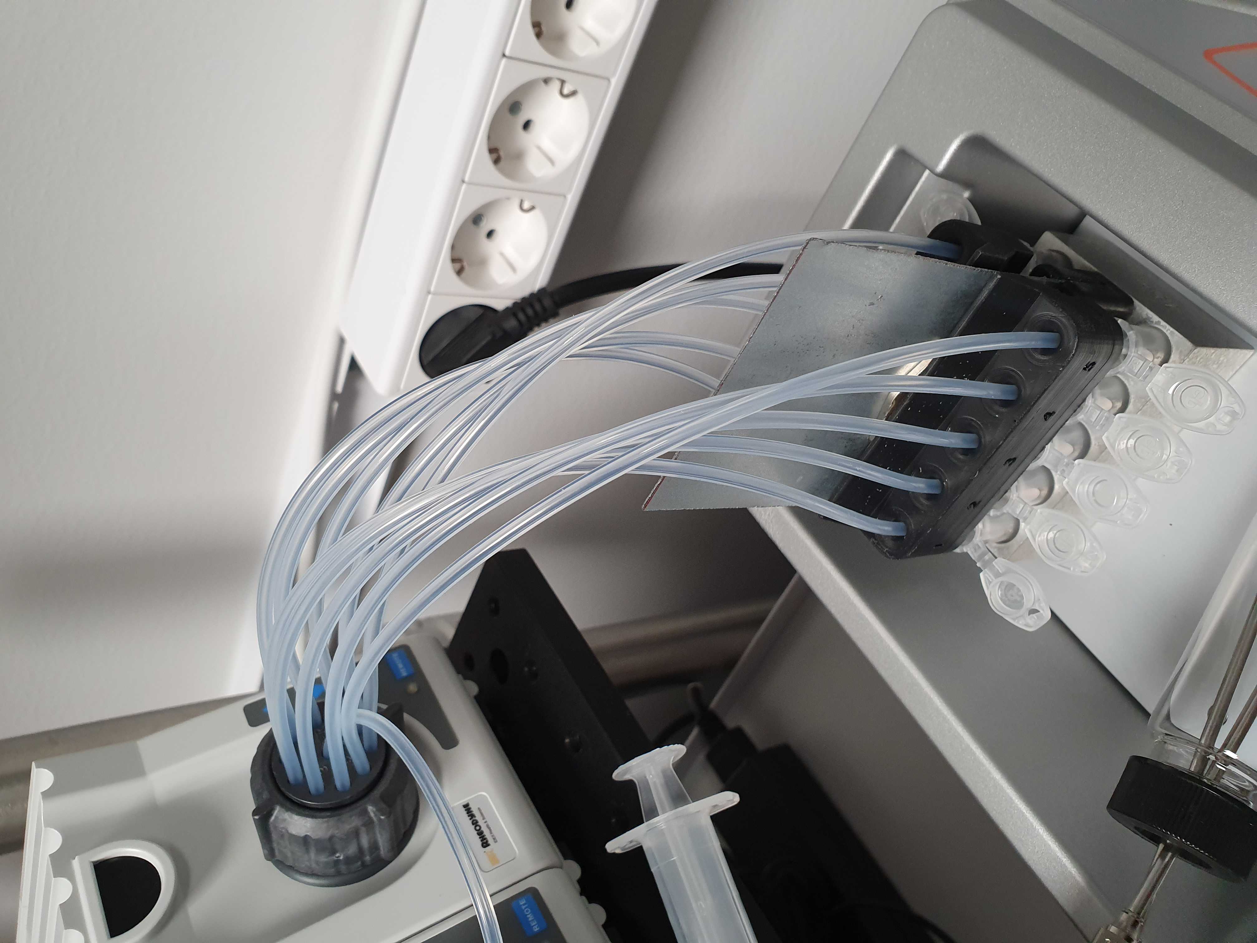
Tubing
Place the hybmix holder in the cold incubator. Optionally use thermal conductive glue or a thermal conductive sticker to firmly secure it in place.
Measure the length of the tubing needed to run form the Right valve to the bottom of an 1.5ml Eppendorf tube. Cut 10 pieces of 1/8 inch OD tubing to this length and diagonally cut the end. Mount them in the valve and run them through the tubing holder. Match the valve number with the number on the printed tubing adapter.


Metal beads
Add Labarmour Beads to the cold incubator to make sure the buffers are in good contact with the cold plate.
Flow cell
There are two options for flow cells in the ROBOFISH system. Either the Rebus Biosystems flow cell or the Bioptechs FCS2. The Rebus flow cell comes with its own temperature controller. For the FCS2, temperature is controlled by a recirculating chiller and you can either use the Solid State Oasis (now called UC 160-190) unit or the ThermoCube.
Place the flow cell on the microscope stage. Place the temperature controller somewhere that you can connect the cables to the flow cell. The cables can be mounted to the breadboard using a Thorlabs CMS010 base with a Thorlabs CMS011 tie wrap and a M6 bolt. Move the stage around and make sure there is enough free cable to allow full movement.


FCS2 Temperature control
Connect at least the bottom heating tubes of the FCS2 to the recirculating chiller. We do not use the top temperature flow option (black ring) because it can pop out when the pressure increases inside the loop. This can happen when you increase the temperature. We have ran successful smFISH experiments using only the bottom tube for temperature control.
To connect to the barbed tubing we used Cole-Parmer Silikon Patin (Tygon 3350, ID 3.2, WS 1.6, AD 6.4mm) tubing. The Oasis and ThermoCube units come with a variety of connection options. Please make sure you can couple the soft tubing attached to the FCS2 to the Oasis or ThermoCube unit. Our ThermoCube has a Swagelok connector that required solid tubing so we had a barbed connector for the soft tubing and connected this to solid tubing using a Quick Release fitting from Parker.
Temperature sensing of the FCS2 is done using an integrated thermistor which can be read out using a Yoctopuce Yocto-MaxiThermistor unit. On the first port of the Yocto-MaxiThermistor unit connect a supplied thermistor to measure the room temperature. Connect the second port to the middle two slots of the FCS2 using electrical wire and two pins.


Connect flow cell
Connect the Y-connector to the flow cell with an appropriate length of 1/16 inch OD tubing to allow full stage movement.
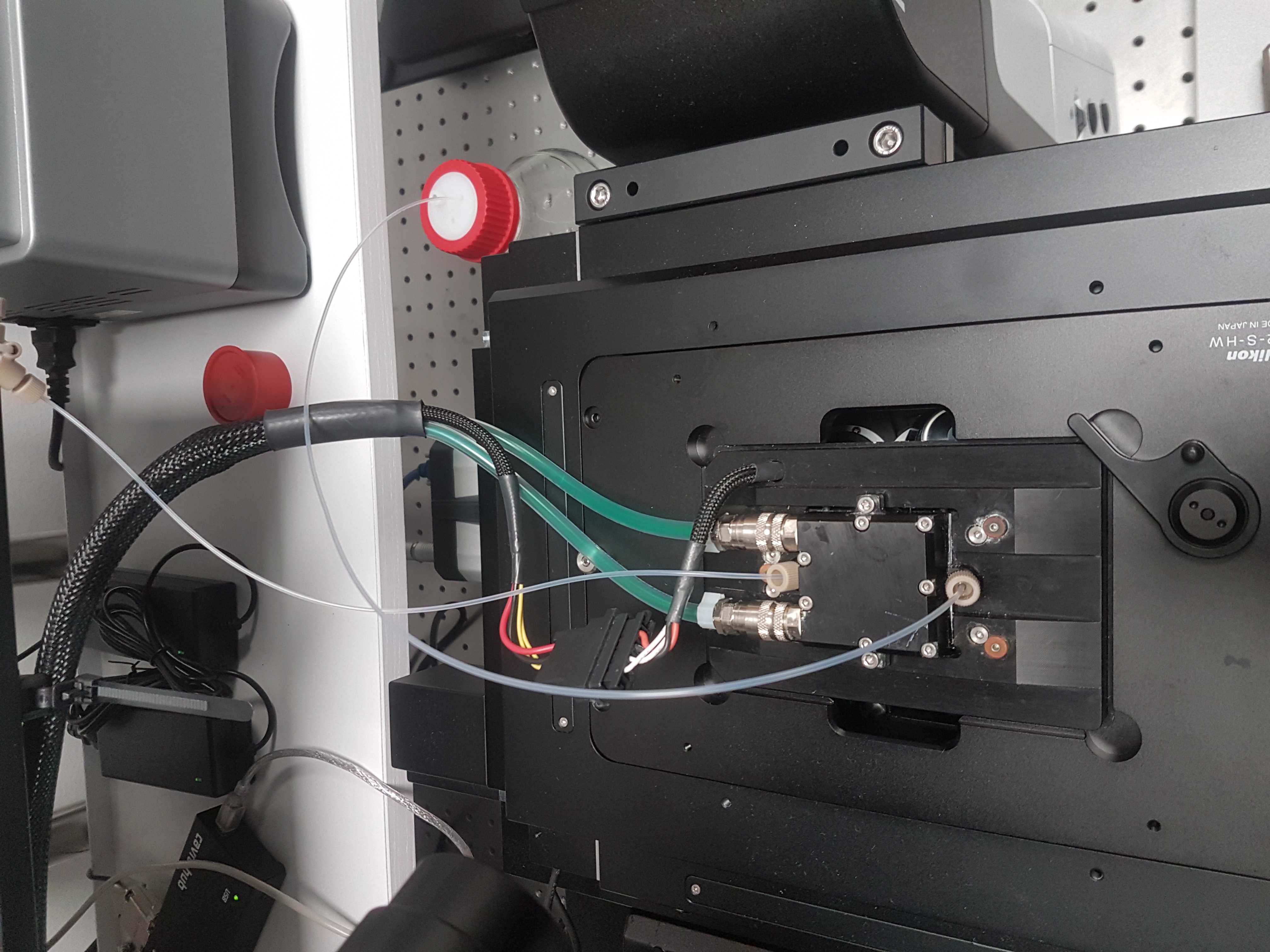
For the FCS2 see the image in the previous step.
Waste bottle
Place an IDEX A-630 cap on a 1 liter bottle and close the big hole with an IDEX A-627 filtered plug. Run an appropriate length of 1/16 OD tubing from the left valve to the waste bottle. The tube should enter the bottle just a few cm. Place the wast bottle on the breadboard with the rest of the machines, so that the hybridization chamber will be the lowest point in the system.
Long tubing lines can be fixed in place by Thorlabs PFS02 cable saddles.
Valves
When all tubes are connected to the valves, make sure they are all pushed all the way to the back. Now, tighten the ring. Make sure it is really tight to prevent leakage.
System operation
Power
Connect the power cables of all machines to an Uninterupted Power Supply. And connect the USB cables of all devices with the computer.
Software installation and Operation
For the software installation and operation of the system please see the code and instructions on the Github page:
