Functional Analysis of Membrane Proteins Produced by Cell-Free Translation
Stefan Kubick, Srujan Kumar Dondapati, Doreen A. Wüstenhagen
Abstract
Cell-free production is a valuable and alternative method for the synthesis of membrane proteins. This system offers openness allowing the researchers to modify the reaction conditions without any boundaries. Additionally, the cell-free reactions are scalable from 20 μL up to several mL, faster and suitable for the high-throughput protein production. Here, we present two cell-free systems derived from Escherichia coli ( E. coli ) and Spodoptera frugiperda ( Sf 21) lysates. In the case of the E. coli cell-free system, nanodiscs are used for the solubilization and purification of membrane proteins. In the case of the Sf 21 system, endogenous microsomes with an active translocon complex are present within the lysates which facilitate the incorporation of the bacterial potassium channel KcsA within the microsomal membranes. Following cell-free synthesis, these microsomes are directly used for the functional analysis of membrane proteins.
Before start
Attachments
Steps
3.1 Preparation of Nanodiscs (NDs)
First prepare 5mg/mL (200micromolar (µM)) containing 20millimolar (mM), 7.4 with 0.1Molarity (M) and 0.5millimolar (mM).
Dissolve DMPC, DOTAP and DOPG lipids in cholate buffer at a concentration of 15millimolar (mM) (see Note 2).
Set up the reactions: mix the lipid solutions (see Notes 3 and 4) with MSP as indicated in Table 1.
Incubate the reactions at 25°C for 0h 30m 0s. Then, biobeads SM-2 are added almost to 80 vol % of the Lipid-MSP mixtures and left to react at 25°C for 0h 45m 0s and then centrifuged at 1000x g. Remove the upper supernatants.
For each reaction , add a second set of 80 vol % biobeads-SM2 and incubate for 0h 15m 0s. After centrifugation at 1000x g, recollect the top solution. The finally recovered solution is further centrifuged at 5000x g and just the top solution (leaving the lower 5µL volume) is recollected and analyzed by zetasizer.
Place 20µL of the recovered solution in a zeta sizer cuvette and measure the size intensity of the particles present in the solution. Figure 1 shows an exemplary measurement: the presence of a strong peak with maximum intensity at around 11.5 nm indicates the presence of NDs.
| A | B | C | D | E | F |
|---|---|---|---|---|---|
| Reaction | DMPC (15 mM) (uL) | DOTAP (15 mM) (uL) | DOPG (15 mM) (uL) | MSP (200 uM) (uL) | Total (uL) |
| 1 | 40 | 10 | - | 50 | 100 |
| 2 | 25 | 25 | - | 50 | 100 |
| 3 | - | 50 | - | 50 | 100 |
| 4 | 50 | - | - | 50 | 100 |
| 5 | - | - | 50 | 50 | 100 |
| 6 | 40 | - | 10 | 50 | 100 |
| 7 | 25 | - | 25 | 50 | 100 |
Table 1Pipetting scheme for reaction setup of NDs

3.2 Membrane Protein Synthesis in Prokaryotic Cell-Free Systems
BR and MtlA proteins are synthesized in cell-free systems using E. coli lysates. A typical 50µL standard reaction comprises:
35% (v/v)40% (v/v)containing the complete amino acid mix (1.2millimolar (mM)each)- 25 × XE-solution (EasyXpress E. coli kit)
1µL- 14C-labeled leucine, final concentration:
50micromolar (µM); 4 DPM/pmol) (see Note 5), and 10% (v/v) of the prepared ND.
Set up the following reactions and controls (without NDs) (Table 2).
Perform the protein synthesis in a thermomixer with shaking at 500rpm,37°C.
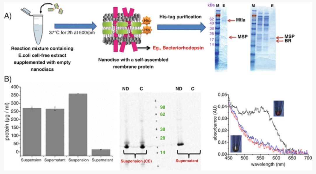
Once the reaction is completed, all the qualitative and quantitative measurements are done by SDS-PAGE combined with autoradiography and TCA precipitation using 14C-leucine. Initially 2 × 5µL of the reaction mixture (suspension) is collected for TCA precipitation and 1 × 5µL for SDS-PAGE analysis. Next, centrifuge the remaining reaction mixture at 16000x g,4°C.
Collect the supernatant into a separate Eppendorf tube. 2 × 5µL of the supernatant is collected for TCA precipitation and 1 × 5µL for SDS-PAGE analysis.
For TCA precipitation, mix 5µL aliquots (both suspension and supernatant) with 3mL and incubate the mixture in a water bath at 80°C for 0h 15m 0s. Afterward, keep the reaction vessel On ice for 0h 30m 0s.
Filter the solution using the vacuum filtration system to retain the radiolabeled proteins on the surface of the filter paper. Wash proteins twice with TCA and twice with acetone, dry the filter papers for some minutes under the hood.
Transfer the dried protein-enriched filter papers to scintillation tubes (Zinsser Analytic), overlay with 3mL and let it shake on the orbital shaker for at least 1h 0m 0s. Measure the incorporation of 14C-leucine by liquid scintillation counting using the scintillation counter.
For SDS-PAGE analysis, precipitate 5µL aliquots (both suspension and supernatant) of the cell-free reaction mixtures by cold acetone precipitation: Add 45µL of the water and 150µL of ice cold acetone to the 5µL aliquot and incubate On ice for 0h 15m 0s. Next, centrifuge the mixture at 16000x g,4°C. Discard the supernatant containing the acetone.
Resuspend the pellets in 20µL and load the samples on precast SDS-PAGE gels. Run the gel at 200 V for 0h 35m 0s. After drying the gels for 1h 10m 0s at 70°C using the Unigeldryer, visualize radioactively labeled proteins with the phosphorimager.
BR in the presence of NDs is folded in a correct form and shows a purple color due to the conversion of all- trans retinal to 11- cis retinal (Fig. 2). Confirm this by analyzing the supernatant samples of BR (Step 10) by UV-Visible spectroscopy for measuring the BR-specific peak.
| A | B | C | D | E | F | G | H |
|---|---|---|---|---|---|---|---|
| Protein | E. coli lysate (uL) | Reaction buffer (uL) | 14^C-Leucine (uL) | Plasmid (5 nM) (uL) | NDs (uL) | Water (uL) | Total (uL) |
| BR | 17.5 | 20 | 1.25 | 2.5 | 5 | 3.75 | 50 |
| MtlA | 17.5 | 20 | 1.25 | 2.5 | 5 | 3.75 | 50 |
| BR | 17.5 | 20 | 1.25 | 2.5 | 0 | 3.75 | 50 |
| MtlA | 17.5 | 20 | 1.25 | 2.5 | 0 | 3.75 | 50 |
Table 2Setup of theE. coli based cell-free synthesis of BR and MtlA proteins in the presence of NDs

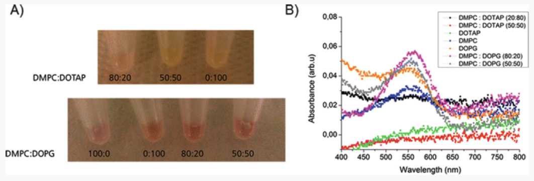
An absorbance peak at around 550 nm corresponds to the purple color of the BR protein. Supernatants from the control reaction (without NDs) should neither produce a purple color nor show an absorbance peak at 550 nm. This indicates that NDs help in correct folding of the BR. Figure 3 3 shows the synthesis of functional BR in the presence of NDs with saturated DMPC lipids doped with cationic (DOTAP) and anionic lipids (DOPG) (Reactions 1 and 6, Table 1). The intensity of the purple color, which indicates the presence of functional BR, varies with lipid composition with higher intensity in the presence of DOPG lipids. This clearly shows that doping of DOPG lipids along with DMPC helps in a better folding of the BR compared to DOTAP lipids. These results suggest that ND with different lipids can have influence on the functionality of the protein [14].

3.3 Membrane Protein Synthesis in Eukaryotic Cell-Free Systems
Cell-free protein synthesis is performed in the linked reaction mode by performing transcription and translation individually ( see Notes 5 and 6 ). Details can be found in Refs. [4, 7]
In the first step, mRNA is generated by transcription from the plasmid DNA (plasmid encoding the KcsA protein, final concentration: 60 μg/mL) or E-PCR product (final concentration: 8 μg/mL) and is incubated for 2h 0m 0s at 37°C. The reaction is performed with 80millimolar (mM), 7.6, 15millimolar (mM) ,3.75millimolar (mM), 0.5millimolar (mM)and 1 U/μL T7 RNA polymerase.
Once the reaction is completed, purify the mRNA using DyeEx spin columns according to the manufacturer’s instructions.
Quantify the purified mRNA using the NanoDrop 2000c. After estimating the concentration, mRNA is used for protein synthesis.
In the second step, translation is performed by adding mRNA at a final concentration of 260microgram per milliliter (μg/mL). To monitor protein quality and quantity, add 14C-labeled leucine to the translation reaction mixture to yield a final concentration of 60micromolar (µM). The translation mixture is incubated for 1h 30m 0s at 27°C.
Quantification of the synthesized protein is done by hot trichloroacetic acid (TCA) precipitation followed by radioactivity measurements as described in Steps 10-13. To analyze homogeneity and molecular weight of in vitro translated proteins, take 5µL aliquots of radiolabeled cell-free translation reaction mixtures for SDS-PAGE analysis using precast gels as explained in Step 14 and in Refs.[4, 5, 6, 6].
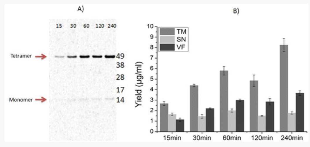
KcsA forms a stable tetramer as seen in Fig. 4a. A prolonged time of translation leads to an increase in the intensity of the tetramer band in the vesicular fraction (VF). These observations correlate with the protein yields for different time periods (Fig. 4b).

3.4 Preparation of Proteoliposomes
Once the protein is synthesized, the vesicular fraction (VF) harboring the synthesized protein of interest is used for functional analysis. One can add either the translation reaction mixture harboring the microsomes and synthesized proteins directly onto the lipid bilayer or prepare proteoliposomes for a faster fusion, as described in the following steps:
50µL of the cell-free translation mixture (TM) is centrifuged at 16000x g,4°C. Supernatant (SN) is separated from the pellet (VF). VF contains the microsomes incorporating the MP of interest.
Resuspend the VF in 0.1Molarity (M) 7.0 by pipetting up and down. Repeat the centrifugation step. After the second centrifugation, separate the SN from the VF. The VF contains the washed microsomes.
Dissolve the washed VF in 50µL. Resuspend vigorously.
Mix 50µL of the detergent resuspended microsomal fraction with 50µL of the 15millimolar (mM) lipid solution of choice (DOPG in our case) and keep the solution for rotation at 300rpm,4°C (see Note 3).
Add Biobeads-SM2 up to 80 vol% of the lipid mixture and incubate further (ON) at 4°C.
After ON incubation at 4°C, spin down all the Biobeads-SM2 by using a short centrifugation step for few seconds and collect the supernatant from the top. The proteoliposomes can be stored at 4°C for few days when measured continuously (see Note 7).
For measuring the activity of the native translocon sec61 pore naturally present in the microsomes, add 30µL to the vesicular fraction and incubate On ice for 0h 45m 0s (VF from step 1 in this section) to get a final concentration of 250micromolar (µM) in 500millimolar (mM). Puromycin combined with high salt concentration unplugs the ribosome from the microsomes and opens the sec61 pore [18].
Centrifuge the microsomal fraction once again at 16000x g,4°C and remove the SN. Prepare the proteoliposomes by repeating the steps 26–30 in this section.
3.5 Formation of Lipid Bilayers
Lipids of interest are dissolved in octane at a concentration of 2 mg/mL. All the stocks of lipids are stored at -20°C.
Lipid bilayers are formed on MECA array chips mounted on the Orbit 16 System [16].
Lipid bilayers are formed as described in [16, 17]: Briefly, 200µL is added to the measurement chamber containing the MECA chip. Once the buffer is added, all the electrodes will be in open (seal resistance of few MΩ).
For the automated bilayer formation on the 16 cavities in parallel, a small amount of approx. 0.1µLis pipetted on to the chip surface and painted with the help of a magnetic bar lying on the MECA chip [16]. Following pipetting of lipids, the bar is moved across the apertures in a circuitious fashion by performing one slow (45–180°/s) rotation of a counter magnet positioned below the chip with the help of the electromotor.
Lipid bilayer formation will be indicated by the change in resistance from MΩ to GΩ (for confirmation of lipid bilayer formation, see Notes 8 and 9).
3.6 Functional Assessment of MPs
Once the lipid bilayer is formed, add 4µL prepared from the puromycin treated native microsomes (no protein synthesized) directly into the buffer chamber containing the lipid bilayers and wait for fusion.
After incubating the lipid bilayer with the proteoliposomes, measure activity from the voltage-clamped lipid bilayers of the sec61 pore by a single channel amplifier single channel amplifier (EPC-10) and the data acquisition software Patchmaster connected to the multiplexer electronics port of the Orbit16 system [14, 15, 16]. Recordings are done at a sampling rate of 50 kHz with a 10 kHz Bessel filter (see "Instrumentation and Software" section in Materials). Unitary currents are recorded from the voltage-clamped lipid bilayers.
Analyze data: Parameters like voltage ramps for monitoring currents are measured by using Patchmaster software and analyzed by the Clampfit software version 10.7.
3.7 Case Study: Exemplary Data for sec61 and KcsA Proteins
Figure 5 shows the functional analysis of native endogenous translocon sec61 protein activity from the microsomal membranes. The diagram shows the typical voltage-gating behavior of native sec61 translocon pore typically present in the microsomes obtained after fusion to the planar lipid bilayer. At lower voltages of −20 and −40 mV, the channel is open without any subconductance states. When the potential is increased to −60, −80, and −100 mV, one can notice the subconductance states. The probability of the channel to be either closed or in one of its open states was constantly reduced at larger potentials. From these activity studies, we observed that the rate of fusion of the protein to the lipid bilayer is increased with modified microsomes (proteoliposomes) when compared to the unmodified. This also shows us the efficiency of the fusion of microsomal proteoliposomes to the lipid bilayer. From Fig. 5a, we can see that with increase in the holding potential, the probability of the channel to be open continuously is reduced [18].

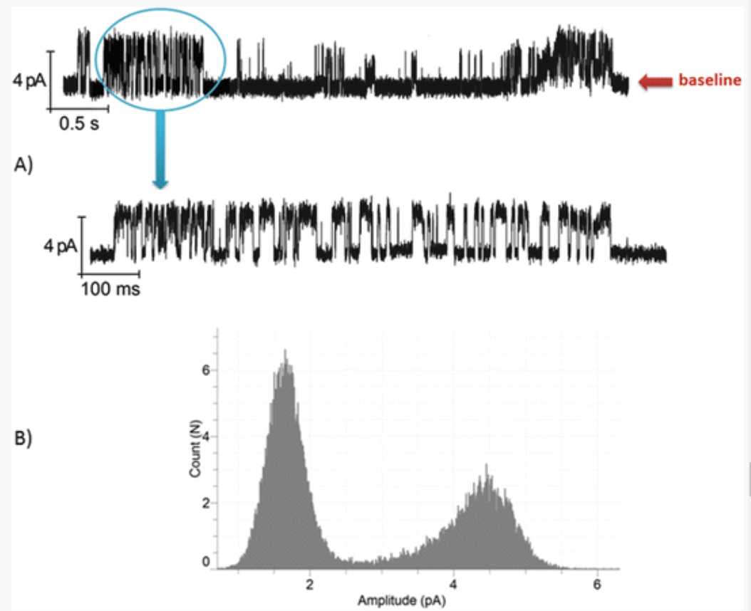
The next step was to prove that this observation is applicable to the newly expressed proteins into the microsomes. The results of the activity measurements of KcsA synthesized in the eukaryotic cell-free system are presented in Fig. 6. After the synthesis reaction, steps 1 and 2 in the Subheading 3.4 were repeated and the microsomes were extracted and used for the functionality measurements. Electrophysiology measurements were recorded and analyzed as shown in Subheading 3.6, steps 2 and 3 . KcsA present in the microsomes showed the functional activity after fusion with the lipid bilayer. Parameters like single-channel conductance events (in the case of KcsA), all point histograms ( see Note 10 ) were measured and analyzed. The protein exhibits a typical single-channel gating characteristic of KcsA at a transmembrane voltage of +60 mV, with a varying mean open time of few ms followed by the closure of the channel (inactivation) [13] ( see Note 11 ).


