Workflow for wooden contact samples in use-wear experiments with bronze axe replicas (MAP-protocol_B)

Ulrich Thaler, Walter Gneisinger

Published: 2021-12-30 DOI: 10.17504/protocols.io.bv2gn8bw

Abstract

Focussing on the role of contact materials as an element of variable control in archaeological use-wear experiments, this protocol sets out a workflow for the preparation, use and documentation of standardized beechwood contact samples. Although developed in the context of rig-based experimentation with bronze axe replicas as part of MAP , it follows principles and sets out procedures of broader applicability within traceological experimental research in general and in studies involving ligneous contact material in particular. MAP (the M ainz, M ayen & M onrepos A xperimental P rogramme) expands into a 'post-lithic' material class (copper-based artefacts) and chronological setting (the Bronze Age) the research agenda developed by TraCEr, which is based on a strong commitment to open science and an understanding of sustained methodological development as a key to consolidating traceology as a sub-discipline within archaeology.TraCEr (the Laboratory for Tra ceology and C ontrolled E xperiments) was established by the RGZM, the Leibniz Research Institute for Archaeology, at the MONREPOS Research Centre and Museum at Neuwied in 2017. Its main scope is to carry out ground-breaking research that combines methodological development, aided by state-of-the-art facilities for controlled experimentation and advanced methods of documentation, and fundamental research on Pleistocene and Early Holocene archaeology.

Fig. 1: The mechanical rig used in MAP, mounted on a workbench, with a 3D-print as a place-holder for the bronze axe replica

Attachments

Steps

Acquisition of contact material

1.

Acquisition of contact material

obtain plank of high-quality beechwood ( Fagus sylvatica ) in a thickness that corresponds to the intended width of your contact samples

48.5 mm thickness (of pre-planed plank, will correspond to contact sample's width)

Note
Practical note: It may be advisable, before a purchase, to enquire whether a supplier regularly stocks beechwood in the specific sorting grade and thickness chosen. In addition, whether it is possible to have blanks for the contact samples cut from the plank by the supplier (cf. step 2.1) may be crucial in choosing a timber shop.

Note
Explanatory comments: Fagus sylvatica: As the product of a deciduous or, more precisely an angiosperm tree species, beechwood is a hardwood, which by contrast with the softwood produced by most coniferous or gymnosperm trees should be conducive to a quicker and/or more pronounced generation of use-wear traces. In addition, it is noted for its homogeneity and, although not a true sapwood species due to the facultative formation of false ('red') heartwood in older trees, traded beechwood is typically sapwood (cf. comment on wood quality below). The sapwood or alburnum is the physiologically active outer part of a living tree’s wood below the bark, facilitating, amongst others, the transport of water, whereas the heartwood does not contain living cells and has undergone chemical and structural changes such as the formation of tyloses, which block water transport. This means that the wood of heartwood species such, e.g., as oak (Quercus robur ) is less suited to the 'forced re-hydration' that is a crucial part of this protocol (cf. step 3). While beech first came to prominence in the post-glacial woods of Central Europe in the Subboreal climatic phase and in many regions was or came to be the dominant forest tree in the Bronze Age, it is also the most common deciduous tree species in considerable parts of Europe today, including Germany, where it accounts for around 17.5 % of the annual wood harvest, which means a consistent and reliable supply. A more extensive discussion of the practical and archaeological reasons for the choice of beechwood as a contact material is presented elsewhere (cf. reference below).wood quality: A higher quality, as indicated by the sorting grade of the procured wood, will mean a lower number of faults, such as e.g. knots, in the wood; in the specific case of beechwood, false 'red' heartwood is also eliminated from higher sorting grades. This means less variation from one contact sample to the next and thus a stronger control of variables in an experimental context. For our current work, we chose the sorting grade ‘Superior’ of Pollmeier Massivholz GmbH & Co.KG, i.e. the highest quality of sawn timber offered by a major German specialist beechwood supplier. This closely corresponds to the ‘FAS’ grade as defined in the United States by the National Hardwood Lumber Association.plank thickness / contact sample width: Our experiments currently use bronze axe replicas of a blade length of approx. 53 mm (variation from 52.2 mm to 54.1 mm across 9 specimens); the plank chosen was traded at a nominal thickness of 52 mm, corresponding to 48.5 mm actual pre-planed thickness. Using contact samples of a width slightly below the blade length allows for contact between sample and contact sample across almost the entire length of the blade while minimizing the risk of leaving uncut 'baulks' at the edge of the contact sample, where the heel or toe of the axe bit may possibly get caught in rig-based experiments with high positional repeatability.

Citation
Ulrich Thaler 2021 Consistency is a beech – on socketed axes, experimental control and ligneous contact materials Paper presented in session 300 of the 27th Annual Meeting of the European Association of Archaeologists

Preparation of contact samples

2.

Preparation of contact samples

2.1.

Cutting of blanks

cut blanks of the intended size (length and height) of your contact samples from the plank or have them cut

500 mm length (blank oriented lengthwise in plank)

80 mm height (of finished blanks, corresponds to width while cutting from plank)

Note
Practical note: With a view to the grain of the wood, the long axis of the contact samples should run parallel to (not across) the long axis of the plank. Given the likely dimensions of the plank, in most cases it will be impractical to perform this step in an experimental lab and results may be less consistent than desired; hence, it will be preferable to choose a supplier that also provides the service of cutting the blanks (and no tools for this task are listed in the materials section of this protocol).

Note
Explanatory comment: We have obtained 18 contact samples from, e.g., a single plank of 300 mm width and 3350 mm length, with a moderate amount of cut-offs. Given a contact sample length of 500 mm and a height of 80 mm, this means that 6 × 3 samples were cut from the plank, with 6 × 500 mm = 3000 mm < 3350 mm and 3 × 80 mm = 240 mm < 300 mm. A yet better fit seems possible since the width of traded planks varies and different standard lengths of 2450 mm and, more importantly, 3050 mm are also available; but material loss from cutting needs to be allowed for and it may not be possible to realize the potential better fit with planks of the latter length.

2.2.

Adaptation to contact sample holder

drill holes through contact samples for mounting on contact sample holder, placing them centrally on longitudinal axis on the top (i.e. the narrowest side)

60 mm distance (of centre of drill-holes from ends of contact sample)

14 mm diameter (of drill-holes / drill-bit)

80 mm depth (of drill-holes, equals height of contact sample)

Equipment

ValueLabel
TB16NAME
pillar drillTYPE
RotwerkBRAND
-SKU
-LINK
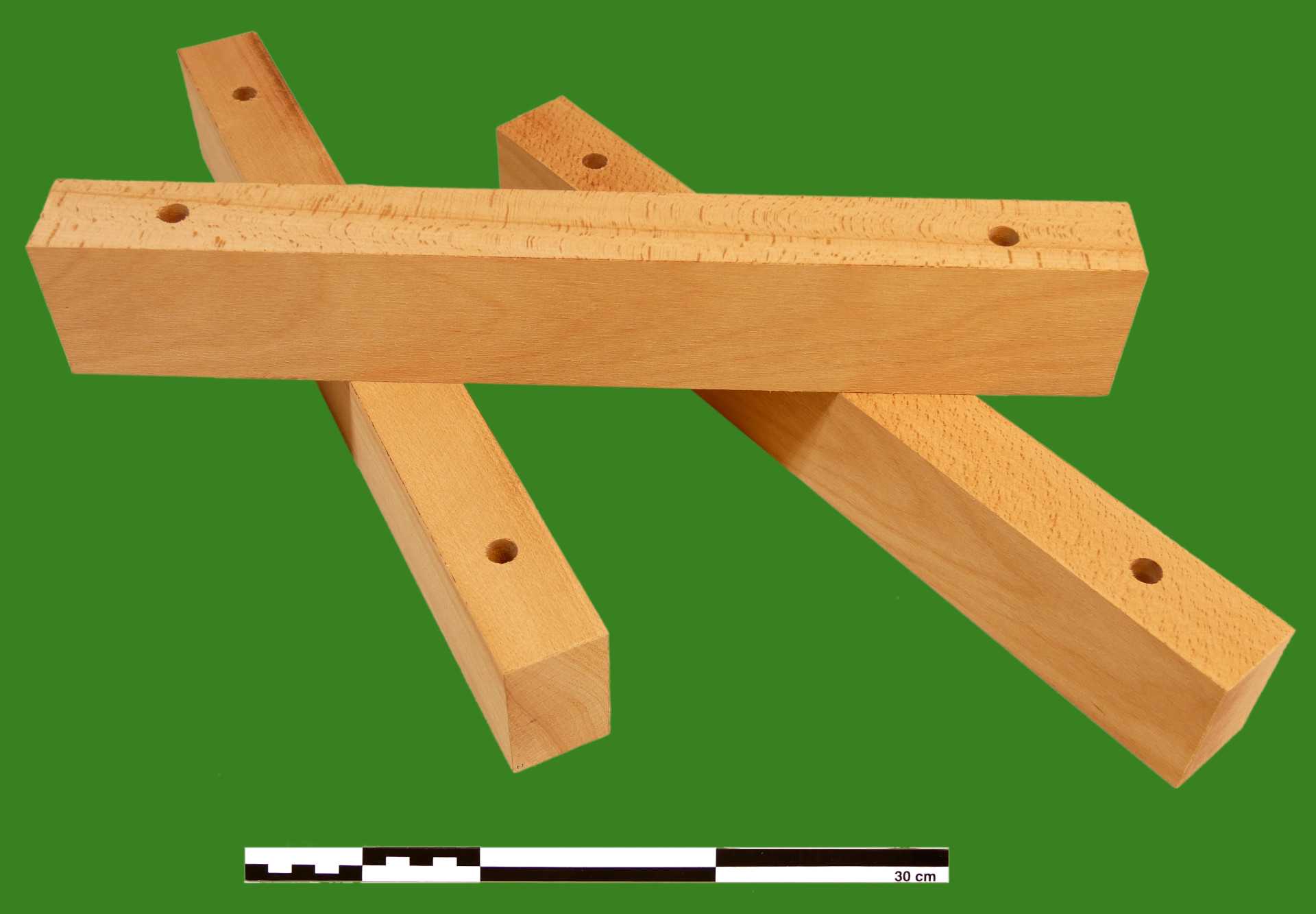
Fig. 2: Contact samples cut to size and with mounting holes drilled

Note
Practical note: The distance from the ends of the contact sample of 60 mm at which the drill-holes are positioned corresponds to a spacing of two threaded rods on the contact sample holder (cf. explanatory comment below), which are set 380 mm apart. The rods' diameter of 12 mm offers, in relation to the 14 mm diameter of the drill-holes, a good compromise between secure fastening and ease of mounting and dismounting of the contact sample.

Note
Explanatory comment: The contact samples prepared in accordance with the present protocol are routinely used with a meachnical rig for use-wear experiments with bronze axe replicas. Inspired by traditional hammer mills, the rig has the axe replica 'hafted' on a long lever mounted on a horizontal axle, meaning the axe head only travels along an arc in a single vertical plane. As a consequence, it is necessary, in order to simulate alternate forehand and backhand strokes and the incremental widening of a notch typical of tree-felling or bucking, to reposition the contact sample relative to the axe head. The latter is achieved through a sample holder rotating on two axes and allowing a linear offset along a third one. Along with the force of impacts, the mobility of the holder necessitates a secure fastening of contact samples, which is facilitated by two threaded rods on the holder which the drill-holes are intended to receive and on which the contact samples is secured with washers and nuts as well as wooden spacers.
Fig. 3: The contact sample holder of the mechanical rig, without (left) and with contact sample mounted (right)
For comparative ('semi-actualistic') trials with handheld bronze axes, a saw-horse has been fitted with wooden brackets to hold the standard-sized contact samples. While the drill-holes are not used to affix the contact sample here (although this would be a viable alternative approach), drilled contact samples are nonetheless used here to facilitate easier comparisons (in terms of, e.g., weight or volume) and to allow batch preparation.
Fig. 4: The saw-horse fitted with wooden brackets as a contact sample holder for manual experiments, without (left) and with contact sample (right)

Conditioning of contact samples

3.

Conditioning of contact samples

bring contact samples to moisture content above fibre saturation point in order to approximate green wood in a controlled manner

Equipment

ValueLabel
VTR 5050 KNAME
vacuum ovenTYPE
HeraeusBRAND
-SKU
-LINK
run with Atlas Copco GVS 16 A (rotary vane pump)SPECIFICATIONS

Equipment

ValueLabel
GVS 16 ANAME
rotary vane pumpTYPE
Atlas CopcoBRAND
-SKU
-LINK

Note
Practical note: The use of a vaccum chamber, as detailed here, considerably speeds up the sorption and absorption of moisture by wood kept under water. But any sort of 'soaking bath' in which wooden contact samples are weighed down until they have largely or completely lost their buoyancy can achieve the same effect.

Note
Explanatory comments: Moisture content: The moisture content (MC) of wood fundamentally influences its physical and mechanical properties and thus is of crucial importance when wood serves as a contact material in use-wear studies. Expressed as a percentage, it is the ratio of the mass of water to the ovendry mass of wood, i.e.MC = mwater/mwood × 100% water/mwood × 100% For practical purposes, it can be calculated by comparing the wet and dry mass of a given piece of wood, i.e.MC = (mwet - mdry)/mdry × 100% The moisture content of green wood can vary considerably, not only between species, but also within a given tree, and ranges from ca. 30% to above 200%.Fibre saturation point: Moisture can be held in wood either through sorption, i.e. as water bound in the cell walls, or through absorption, i.e. as liquid water or vapour contained in cell lumina or cavities. The moisture content at which, in principle, the cell walls are fully saturated, but no free water is as yet found is referred to as the fibre saturation point (FSP). With some variation, it typically lies at about 30% and is, crucially for present purposes, considered as the point from which on additional moisture will not change the physical and mechanical properties of wood.

Citation
Samuel V. Glass, Samuel L. Zelinka 2010 Moisture Relations and Physical Properties of Wood In: Wood Handbook. Wood as an Engineering Material (Centennial Edition), pp. 4-1–4-19

Note
Side-note on alternative approach for contact sample conditioning: Wood stored in a stable atmosphere, i.e. in air of a given relative humidity and temperature (rather than under water), will attain, over time, a stable moisture content specific to those atmospheric conditions; this is called the equilibrium moisture content (EMC). Since a moisture content of 12%, the equilibrium moisture content in standard climatic conditions of 20°C and 65% RH, is a common reference value for the determination of physical and mechanical characteristics of wood, this was explored as an alternative approach for conditioning wooden contact samples for use-wear experiments. Preliminary results in trials with bronze axe replicas were not especially encouraging, with the higher 'resistance' the comparatively dry wood offered to the replicas leading to relatively rapid blunting. The approach may have advantages, however, in the context of other use-wear experiments and may still deserve re-visiting for further studies with bronze axe replicas.

3.1.

Priming vacuum pump

after ensuring that the gas ballast valve of the vacuum pump is open and the valve connecting the pump to the vacuum chamber is closed, start the vacuum pump and leave to idle for 20 minutes

0h 20m 0s

Note
Explanatory comment: When pumping atmospheric air in a vacuum system, the pumped air will invariably contain some water vapour. As there is a water immersion tank, i.e. the soaking vat (cf. step 3.3), contained in the vacuum chamber of this experimental setup, this effect is enhanced due to an increasing vacuum which converts the liquid phase into a gas phase to contribute to the overall contamination. During the compression process in the pump, this water vapour will condense. Failure to remove it will form a contaminant in the sealing oil, prevent the pump from achieving its optimum vacuum pressure and will ultimately be detrimental to the pump itself. A gas ballast valve incorporated into the system will allow a flow of ballast gas (here: air) into the final part of the compression cycle of a mechanical, oil sealed vacuum pump. It allows the vapour to be expelled without condensation and resulting contamination of the sealing oil but pumping with an open gas-ballast valve will affect the ultimate pressure of the pump. To further reduce the harmful effects of condensate formation in the pump, it is allowed to pump against a closed chamber evacuation valve for 20 minutes with an opened gas-ballast valve prior to opening the chamber valve to evacuate the chamber. This way the increased operating temperature of both oil and pump will decrease the formation of condensate.

3.2.

Weighing contact samples

(can run parallel to 3.1)

weigh contact samples (triple measurement); record result(s) along with the date

Equipment

ValueLabel
PCB 3500-2NAME
precision balanceTYPE
KernBRAND
-SKU
-LINK

Note
Practical note: For the recording of measurements, a template for Microsoft Excel is provided with this protocol ("contact-sample-log_template_2021-06-28.xlsx", with sections colour-coded in accordance with this protocol), which performs a number of calculations automatically (indicated by darker shading of fields), including that of the mean of three measurements to be entered in the block entitled "conditioning". It also calculates 'target weights' for the conditioning process, based on the pre-conditioning weight and the (hypothetical) assumption that a moisture content of 35% be reached starting from a pre-conditioning moisture content of 0%. Since the latter corresponds to fully ovendry wood, the 'target weight' will be an over-estimate for any contact sample already containing any moisture, meaning that if the calculated 'target weight' is reached or surpassed, a moisture content above 35% and thus well above fibre saturation point can be safely assumed.https://content.protocols.io/files/dv2sbg497.xlsx

3.3.

Loading vacuum chamber

(can run parallel to 3.1)

stack contact samples in soaking vat in open-pile fashion with stickers, placing weight on top to counteract boyancy, fill vat with (tap) water up to level of weight and place vat in vacuum chamber
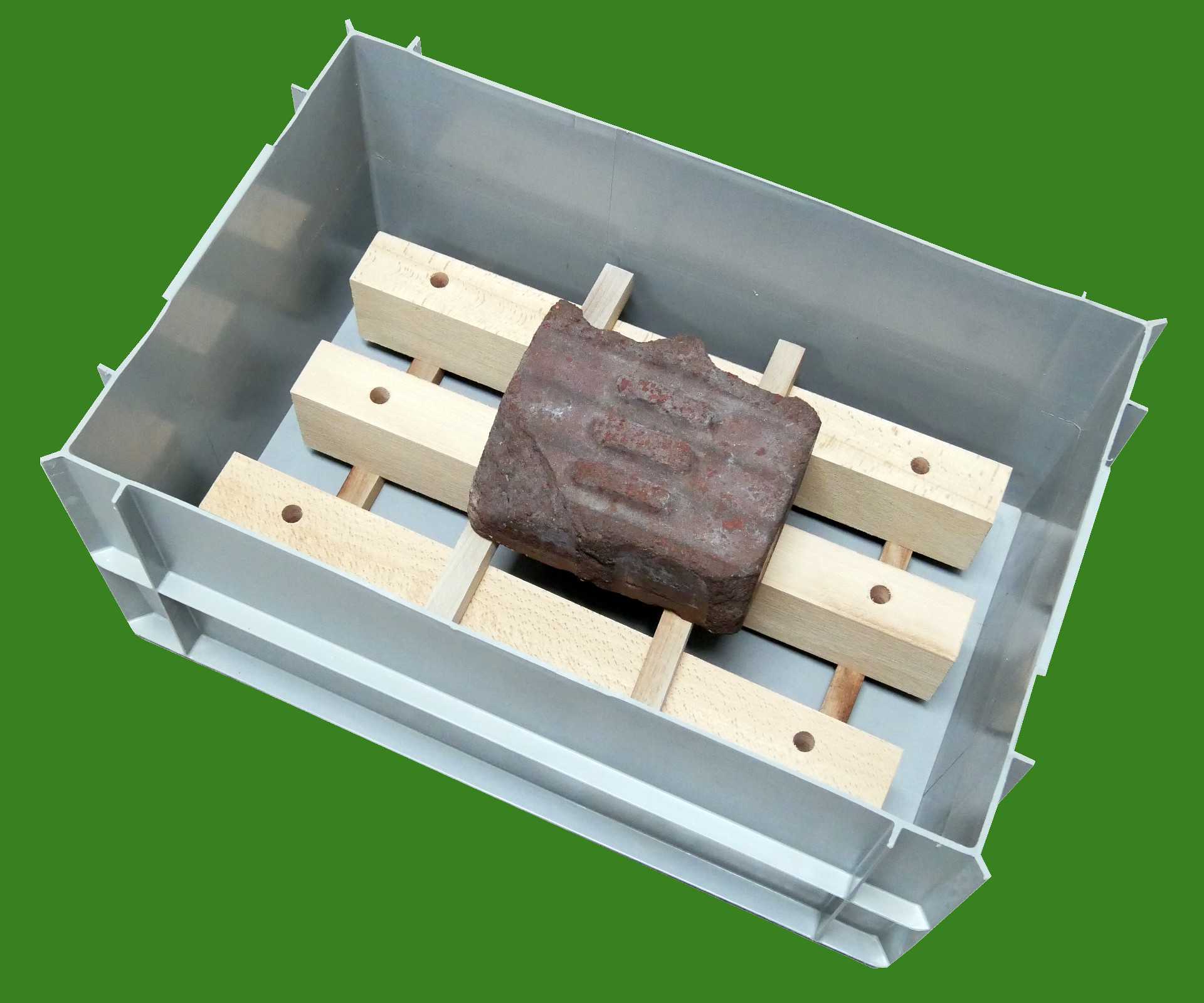
Fig. 5: Soaking vat with contact samples stacked in open-pile fashion and weighted down, ready for submersion

Note
Practical note : Contact samples should be used soon after conditioning, i.e. typically on the same day, since storage may effect the moisture content (depending on conditions) and the wet wood can be prone to fungal growth. This means that the number of contact samples in any conditioning cycle should be adjusted to the needs of the next days experiments and will tend to be low. With two stickers (cf. explanatory comment below) of a length slightly less than the width of the vat needed for every layer of contact samples in the stack, plus an additional two for placing the weight, a total of four stickers will usually suffice, but it may be helpful to keep spares.

3.4.

Closing vacuum chamber

(can run parallel to 3.1)

once loaded, close vacuum chamber, taking care to only lightly fasten the clamping levers of the door ('finger-tight') and ensuring that the ventilation valve on the door is closed

3.5.

Evacuating chamber

by slowly opening the chamber evacuation valve connecting the pump and vacuum chamber, evacuate the chamber; observe pressure gauge and leave valve open for 1 hour after the reading has stopped falling

1h 0m 0s
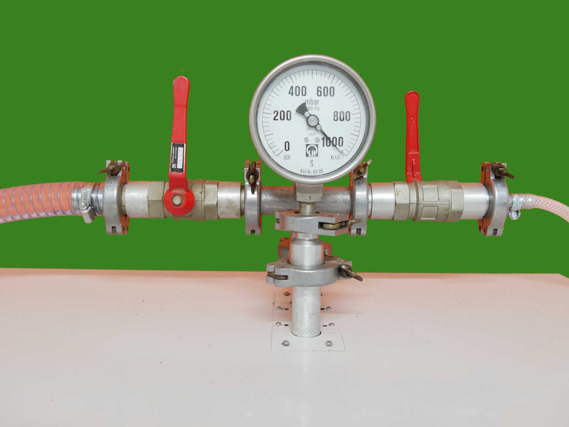
Fig. 6: Pressure gauge and fully closed chamber evacuation valve (on left) of vacuum chamberNote the faint felt-tip mark on gauge indicating the minimum pressure established in previous trials, at a reading of slightly below 50 mbar. The red leaver on the right belongs a valve connecting to a secondary vacuum container not used in the present protocol; accordingly, that valve is also fully closed and remains so throughout.
3.6.

Safeguarding against condensation in pump

slowly close the chamber evacuation valve and leave vacuum pump to run on idle for 15 minutes, turning it off only after that time has elapsed

0h 15m 0s

Note
Explanatory comment: As set out above (cf. step 3.1, explanatory comment), reducing the amount of condensate in the vacuum pump is recommended practice. For this reason, after achieving the target vacuum in the vacuum chamber, the chamber evacuation valve is closed and the vacuum pump is allowed to pump with an open gas ballast valve for a further 15 minutes. This way, any residual condensate is expelled from the pump prior to switching it off.

3.7.

Sorption and absorption

leave the contact samples in the evacuated chamber overnight

3.8.

Opening vacuum chamber

open the ventilation valve on the vacuum chamber door, checking that the door clamping levers do not tighten too much while waiting for normal atmospheric pressure to be re-established inside the chamber; once normal pressure is reached, open door

3.9.

Weighing contact samples

weigh contact samples (triple measurement); record result(s) along with the date; compare weight to 'target weight'

Equipment

ValueLabel
PCB 3500-2NAME
precision balanceTYPE
KernBRAND
-SKU
-LINK

Citation
check ifactual weight > target weight If this has been achieved, continue to step 4. If this has not been achieved, repeat steps 3.1, 3.3–3.9.

Note
Practical note: A 'trade-dry' (i.e. moisture content of approx. 7–9%) beech contact sample of the kind described in this protocol should reliably reach a moisture content of approx. 100% overnight, following the procedure set out above. In comparative trials with fully oven-dry, but otherwise identical beech specimens as well as with partially dried spruce samples collected as roundwood of approx. 80–120 mm in diameter, several 'hydration cycles' were needed to obtain comparable results or even a moisture content clearly above fibre saturation; for this reason, the template file "drying-log_template_2021-06-28.xlsx" includes a column for the recording of cycles (abbreviated 'cyc.' in the column head).https://content.protocols.io/files/dv2tbg497.xlsx

Use-wear experimentation

4.

Use-wear experiment

4.1.

Weighing contact samples and measuring moisture content

weigh contact samples (triple measurement) immediately before experimental use (for the contact sample used first after the opening of the vacuum chamber, a new measurement may not be needed); measure moisture content with hand-held moisture meter (triple measurement in different spots); record results along with the date

Equipment

ValueLabel
PCB 3500-2NAME
precision balanceTYPE
KernBRAND
-SKU
-LINK

Equipment

ValueLabel
Moisture Detector MDNAME
hand-held electric moisture meter (conductance meter)TYPE
BrennenstuhlBRAND
-SKU
-LINK

Note
Practical note: The electrical method of moisture determination cannot match the oven-drying method (cf. below, step 6) in terms of accuracy, but is far quicker and does not change the measured moisture content. Besides such general reservations, the Brennenstuhl MD in particular has a measuring range of 5–50% for wood and is thus not suited to exactly determine the moisture levels likely encountered at this point (nor is it, indeed, intended for that purpose by the manufacturer). It is here employed merely to double-check that a moisture content in excess of fibre saturation has been reached. Despite this inherent inaccuracy, a triple measurement (with use of the instrument in three different spots) is recommended to control for intra-sample variation.

4.2.

Use of sample on contact sample

record sample used on contact sample

Note
Practical note: At this point the workflow for contact samples will intersect with the workflow for samples (and possible further elements of experimental protocols); future versions of the present protocol are intended to include a schematic representation this intersection (or possibly several such representations, as this workflow is intended for application in different experiments). Documentation at this point is likely to focus on the samples (and their use) more than the contact samples; as a likely minimum requirement in terms of documentation, the template file "drying-log_template_2021-06-28.xlsx" includes a column for the recording of the sample used on any given contact sample.https://content.protocols.io/files/dv2ubg497.xlsx

4.3.

Weighing contact samples and measuring moisture content

weigh contact samples (triple measurement) immediately after experimental use; measure moisture content with hand-held moisture meter (triple measurement in different spots); record results

Equipment

ValueLabel
PCB 3500-2NAME
precision balanceTYPE
KernBRAND
-SKU
-LINK

Equipment

ValueLabel
Moisture Detector MDNAME
hand-held electric moisture meter (conductance meter)TYPE
BrennenstuhlBRAND
-SKU
-LINK

Note
Practical note: The template file "drying-log_template_2021-06-28.xlsx" will automatically calculate the weight (strictly speaking: mass) removed from the contact sample in the course of the experiment. For experiments with bronze axe replicas this can be considered a first proxy for the efficiency of the work undertaken.https://content.protocols.io/files/dv2vbg497.xlsx

Photographic documentation

5.

Photographic documentation

Note
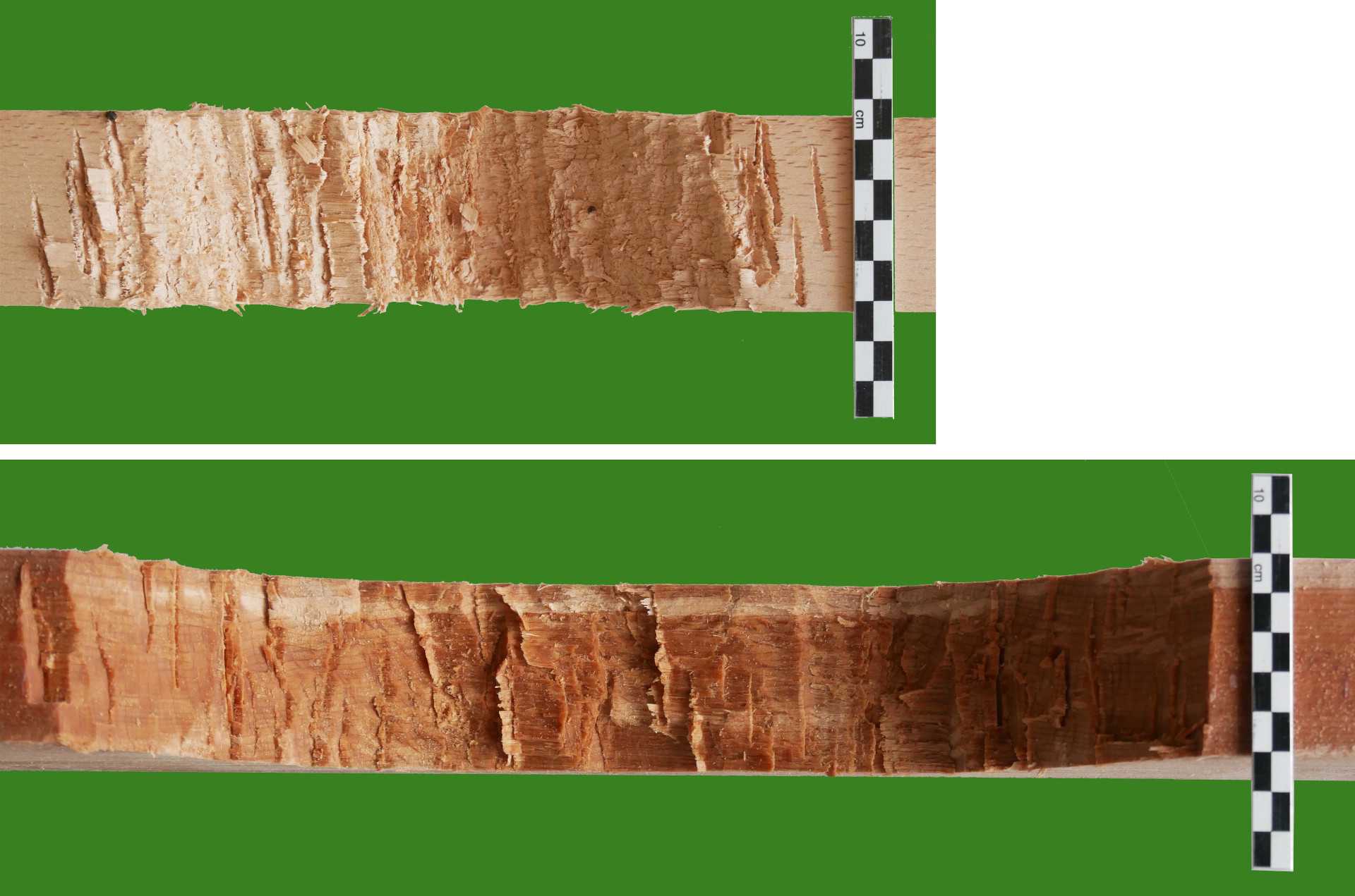
Explanatory comment: Even if the use-wear on the sample is what traceological experiments are ultimately concerned with, the work-traces on the contact samples can be highly informative as well. Hence, it makes good sense to not only archive contact samples whenever possible for future reference (cf. step 7), but also to undertake basic photographic documentation immediately upon finishing an experiment. A scale bar should always be included, while a colour reference card is not deemed necessary; given the moisture dependence of the colour of wood, it would merely offer information on moisture content, an attribute more adequately recorded by other means (cf., in particular, step 6).

Fig. 7: Comparison of notches obtained by 1000 strokes with hand-held axe on contact sample conditioned to 12% moisture content (top; cf. step 3, side-note on alternative approach for contact sample conditioning) and in accordance with the present protocol (bottom).While documenting contact samples from 'semi-actualistic' rather than rig-based trials, the photos clearly illustrate the informative potential of observations on contact samples, showing the contrast between a relatively narrow notch with some indication of crushed rather than cut fibers above and a wider notch with clear cutting facets below.
5.1.

Documentation of full view

take image of full view, including a scale bar, angled to give an idea of the three-dimensional quality of the contact sample

5.2.

Documentation of notch

take detail image of notch as vertical shot, including a scale bar

5.3.

Comparative documentation

Optionally, further images may be taken to directly compare contact samples.

Determination of moisture content (oven-drying method)

6.

Determination of moisture content (oven-drying method)

determine precise moisture content by oven-drying contact sample until weight constancy is reached, i.e. until weight discrepancy between two measurements at least two hours apart falls below 1‰

Equipment

ValueLabel
UT 6120NAME
air-circulation drying ovenTYPE
HeraeusBRAND
-SKU
-LINK
6.1.

Loading drying oven

place contact samples in drying oven set to 103°C, recording starting date of oven-drying for each

Note
Practical note: The starting date of oven drying can be recoreded in the main recording template provided with this protocol ("drying-log_template_2021-06-28.xlsx"). The corresponding colum head reads "start datedry".https://content.protocols.io/files/dv3wbg497.xlsx

6.2.

Oven-drying

leave drying cabinet to run at 103°C on at least 3 to 5 (preferably consecutive) days (period may be shortened in repeat cycles)

Note
Practical note: In some laboratories, as is the case in ours, in-house rules may designate the drying-oven as a piece of equipment that may not be left running overnight without direct oversight. Since a degree of resorption will take place whenever the drying-oven is turned off, this will inevitably lengthen the drying process. The above-indicated period of 3 to 5 days is established on the basis of the drying-oven available in our lab and the regulations pertaining to its use. Considerably shorter drying durations may be achieved elsewhere.

6.3.

Weighing contact samples

weigh contact samples (triple measurement); record result(s) along with the date and time for each

Equipment

ValueLabel
PCB 3500-2NAME
precision balanceTYPE
KernBRAND
-SKU
-LINK

Note
Practical note: Since repeated measurements may be needed that would not fit the main recording template for Microsoft Excel provided with this protocol ("drying-log_template_2021-06-28.xlsx"), an additional Microsoft Excel template is provided for recording the oven-drying procedure ("drying-log_template_2021-06-28.xlsx"). In the latter, a separate rider should be created for each contact sample recorded (typically each sample in a given batch dried at the same time) and named with the contact sample's identifier. The 'wet' weight of the contact sample directly after the experiment should be copied into the respective field of the drying template from the main template as a crucial reference for automated calculations; the moisture content as determined by hand-held moisture meter upon completion of the experiment can also be entered for reference purposes, but is not used by automated calculations in the template. A calculation of moisture content will be automatically perfomed by the template whenever a weight is entered; until weight constancy has been reached, the automatically calculated values will not correspond to the actual moisture content (as of the beginning of oven-drying), but constitute minimum estimates thereof. As in the main template, fields automatically calculated are indicated by darker shading.https://content.protocols.io/files/dv2xbg497.xlsx In addition, the starting date of weight recording should be recoreded in the main recording template provided with this protocol ("drying-log_template_2021-06-28.xlsx"). The corresponding colum head reads "start daterec.".https://content.protocols.io/files/dv3wbg497.xlsx

6.4.

Waiting period / continued oven-drying

let (a minimum of) two hours elapse before next weight check

2h 0m 0s

6.5.

Weighing contact samples and checking weight discrepancy

weigh contact samples (triple measurement); record result(s) along with the date and time for each; compare weight recorded in step 6.3

Equipment

ValueLabel
PCB 3500-2NAME
precision balanceTYPE
KernBRAND
-SKU
-LINK

Citation
check if(weight6.5 - weight6.3)/weight6.3 × 1000‰ 6.5 - weight6.3)/weight6.3 × 1000‰ < 1‰ If this has been achieved, continue to step 6.8. If this has not been achieved, return sample to oven and continue to step 6.6.

Note
Practical note: When a time, but no date is entered along with a measured weight, the file template for the oven-drying procedure ("drying-log_template_2021-06-28.xlsx") will automatically calculate the weight change from the last recording to the present one, i.e. perform the check noted above. If the criterion for weight constancy, i.e. a weight change of <1‰, has been reached, the weight change will be highlighted in green.https://content.protocols.io/files/dv2xbg497.xlsx In addition, the end date of weight recording should be recoreded in the main recording template provided with this protocol ("drying-log_template_2021-06-28.xlsx") and the values for weight and moisture content copied to it from the oven-drying template.https://content.protocols.io/files/dv3wbg497.xlsx

6.6.

Waiting period / continued oven-drying

let (a minimum of) two hours elapse before next weight check

2h 0m 0s

6.7.

Weighing contact samples and checking weight discrepancy

weigh contact samples (triple measurement); record result(s) along with the date and time for each; compare weight recorded in step 6.4

Equipment

ValueLabel
PCB 3500-2NAME
precision balanceTYPE
KernBRAND
-SKU
-LINK

Citation
check if(weight6.7 - weight6.5)/weight6.5 × 1000‰ 6.7 - weight6.5)/weight6.5 × 1000‰ < 1‰ If this has been achieved, continue to step 6.8. If this has not been achieved, return sample to oven and repeat steps 6.2–6.5 (or, if needed) 6.2–6.7).

Note
Practical note: When a time, but no date is entered along with a measured weight, the file template for the oven-drying procedure ("drying-log_template_2021-06-28.xlsx") will automatically calculate the weight change from the last recording to the present one, i.e. perform the check noted above. If the criterion for weight constancy, i.e. a weight change of <1‰, has been reached, the weight change will be highlighted in green.https://content.protocols.io/files/dv2xbg497.xlsx In addition, the end date of weight recording should be recoreded in the main recording template provided with this protocol ("drying-log_template_2021-06-28.xlsx") and the values for weight and moisture content copied to it from the oven-drying template.https://content.protocols.io/files/dv3wbg497.xlsx

6.8.

Calculation of moisture content

calculate and record the moisture content of the contact sample(s) using the formula

MC = (mwet - mdry)/mdry × 100%

in which mwet is the weight(/mass) recorded in step 4.3 and mdry is the lowest weight(/mass) recorded in steps 6.3, 6.5 and 6.7 (N.B.: not the lowest single measurement, but the lowest weight calculated as the mean of triple measurement)

Note
Practical note: When using the file template for the oven-drying procedure ("drying-log_template_2021-06-28.xlsx"), this calculation will already have been perfomed automatically (cf. steps 6.5 and 6.7, practical note), but the result should be copied to the main template.https://content.protocols.io/files/dv2xbg497.xlsx https://content.protocols.io/files/dv3wbg497.xlsx

6.9.

Calculation of further attributes

Optionally, further attributes may be calculated at this point.

Note
Practical note: As but one example of further attributes, the main recording template ("drying-log_template_2021-06-28.xlsx") will automatically calculate an oven-dry equivalent for the weight(/mass) removed from the contact sample during experimentation (cf. step 4.3). The cuboid form of the samples, with two cylindrical drill-holes, aids further calculations. In particular, it permits the calculation of volume, from which density can be derived. While expansion, shrinkage and warping can be observed throughout the treatment of the contact samples (with moisture contents varying between oven-dry and well above fibre saturation), the fact that contact samples have been cut to specified dimensions at a 'trade-dry' moisture content of approx. 7–9% should allow an operationally reliable approximation of their dry volume.https://content.protocols.io/files/dv2wbg497.xlsx

Storage

7.

Storage

archive contact samples alongside samples
Note
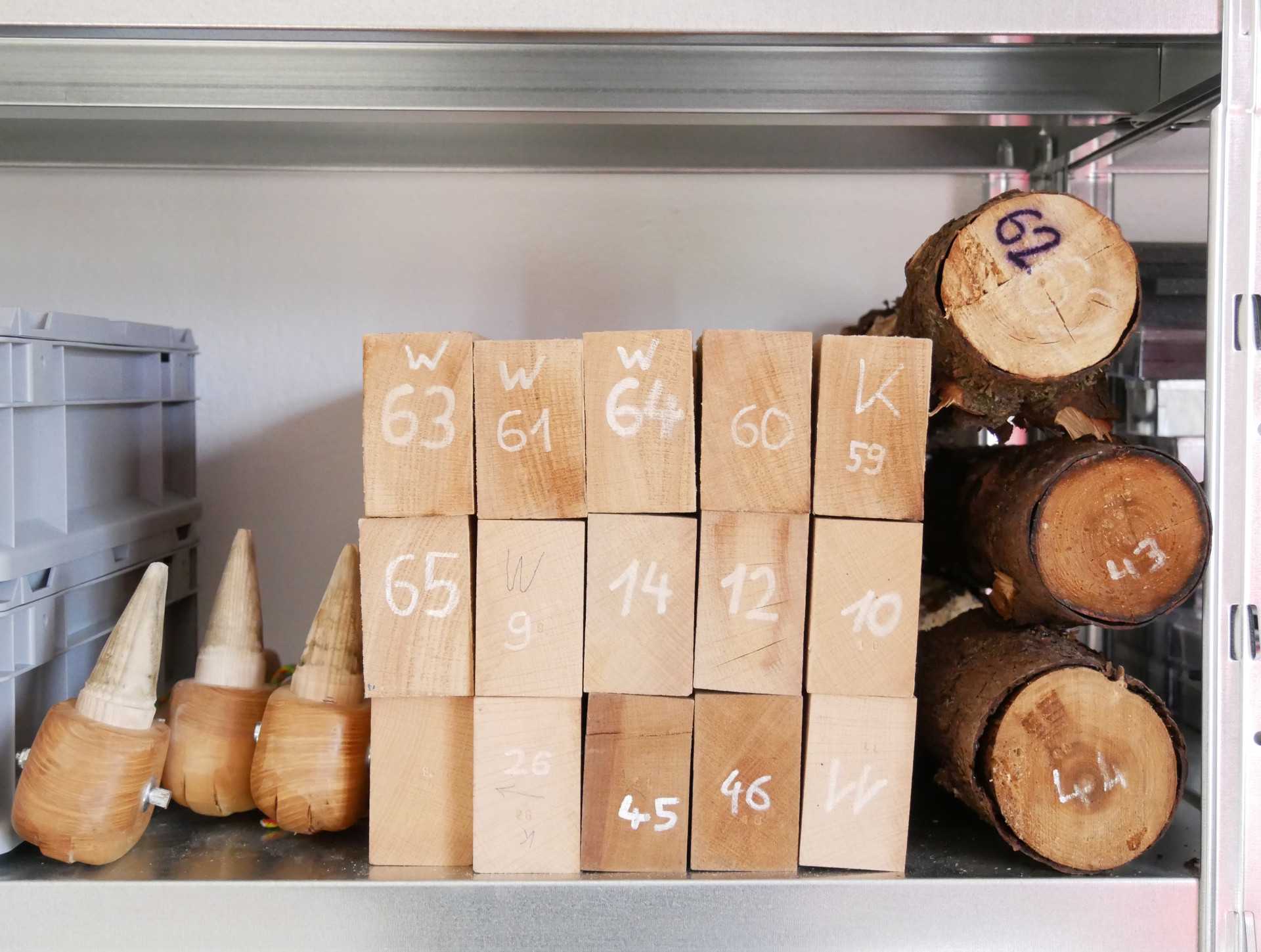
Explanatory comment: As indicated before (cf. step 5, explanatory comment), the work-traces on the contact samples can be highly informative, even if the use-wear on the sample is the primary source in experimental traceology – as it is in the traceological study of archaeological samples, where the contact material is typically not available for examination. In experimental traceology, contact samples can be examined and hence it is deemed good practice to archive them for future reference. The cuboid shape of the contact samples used in the present protocol allows for easy and efficient (solid-pile) stacking.

Fig. 8: Contact samples prepared and treated in accordance with the present protocol in post-trial storage, shelved between axe handles (left) and roundwood contact samples (right)Despite some warping evident particularly on the left side of the solid-pile stack, the cuboid contact samples are clearly more suited to economizing shelf-space than their roundwood counterparts.

推荐阅读

Nature Protocols
Protocols IO
Current Protocols
扫码咨询