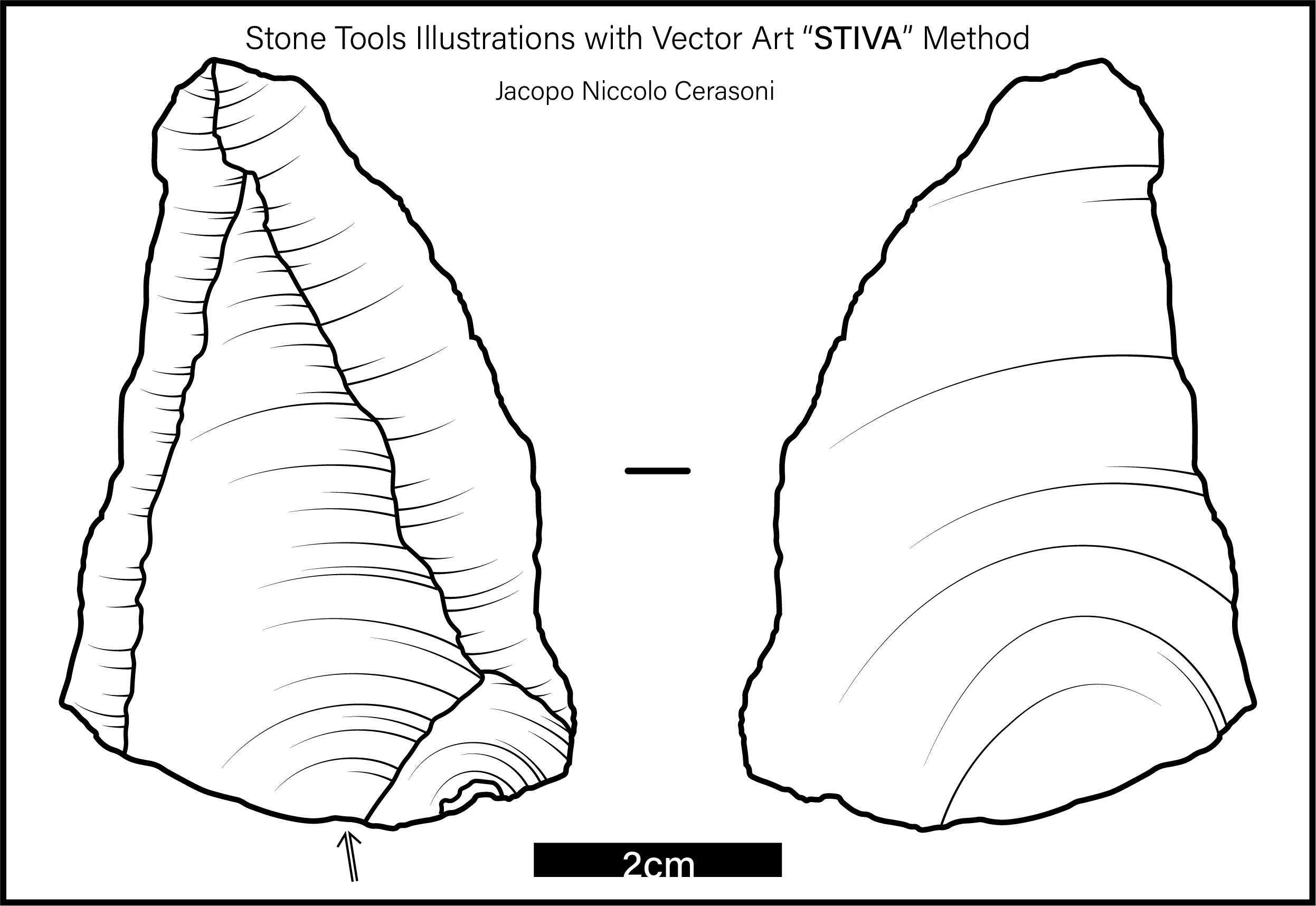
Stone Tools Illustrations with Vector Art: The 'STIVA' Method
Jacopo Niccolo Cerasoni
Stone Tools
Lithics
Illustration
Archaeology
Anthropology
Prehistory
Material Culture
Technical Drawing
Abstract
Lithic illustrations are often used in scientific publications to efficiently communicate the technological and morphological characteristics of stone tools. They offer invaluable information and insights not only on how stone raw materials were transformed into their final form, but also on the individuals that made them. Here, the “Stone Tools Illustrations with Vector Art” (STIVA) Method is presented, which involves the illustration of lithic artefacts using vectorial graphics software (Adobe® Illustrator®). This protocol follows an optimised step-by-step method, presenting ten major sections that constitute the creation of a lithic illustration: photography, vectorial software configuration, scale, outline, scar borders, ripples, cortex, symbols, composition, and export. This method has been developed to allow researchers, students and educators to create clear and competent illustrations for any application, from scientific publications to public outreach.(The last step contains a supplemental video with extra context and tips, as part of the protocols.io Spotlight series, featuring conversations with protocol authors.)
Before start
Steps
Photograph Artefact
Lock camera on a tripod (ideally use a macro lens with a focal length of between 90mm to 105mm) and place in light box (if available).
Place artefact flat onto the workspace.
If the artefact does not sit flat due to its irregular shape, use an appropriate amount of modelling clay wrapped in plastic wrap so to create a modellable support surface.
With lamps or other light-sources set up direct and suffused lighting from one or more sides and the top. Scar shadows should appear. Try to prevent major shadowing on the background surface.
Take several photographs of the artefact, moving the lighting at different angles and heights so to create different shadow orientations.
Select the preferred photograph, which should have the highest degree of visibility of the single scars and ripples.
Repeat processes 2 - 5 for the remaining sides of the artefacts which you want to illustrate (e.g. ventral face, dorsal face, profile, platform).
Choose the photographs that will be used in the next steps, and save them in a separate folder. Do not delete the remaining photographs.
Open and Configure Vectorial Graphics Software
Open Adobe® Illustrator®.
Select: Create new > choose size of preference
Set the workspace to tracing: Window > Workspace > Essentials Classic

Set up the layers that will be used using the Create new layer button.
Create the following layers in ascending (bottom to top) order: “background”, “base photograph”, “cortex” (only if present), “outline”, “scars borders”, “ripples”, “symbols” (only if present), and “scale”.

Upload Photograph
Select the layer "base photograph", making sure the layer is highlighted in blue in the Layers tab.
Insert (import, drag or copy and paste) the previously selected photograph onto the layer.
Lock layer “base photograph” by clicking the lock icon.

Add Scale
Decide how long the scale will be (common scale lengths are: 1cm, 2cm, 5cm, 10cm and 20cm).
Trace the selected length scale over the “base photograph” scale with the Rectangle Tool.

Illustrate Artefact Outline
Use Curvature Tool to trace the outline of the artefact as a closed path. This action should be done while at a high level of magnification and using a medium to thin line stroke thickness, so to maintain as much detail as possible.
<img src="https://static.yanyin.tech/literature_test/protocol_io_true/protocols.io.cghitt4e/i847bgrsx7.jpg" alt="Completed "outline" layer showing drawn anchor points." loading="lazy" title="Completed "outline" layer showing drawn anchor points."/>
Lock layer "outline".
Illustrate Scars Borders
Use Curvature Tool to trace the scars borders of the artefacts as open paths. Set the thickness of the paths at the same thickness of the artefact outline.
<img src="https://static.yanyin.tech/literature_test/protocol_io_true/protocols.io.cghitt4e/i849bgrsx16.jpg" alt="Completed "scars borders" layer showing drawn anchor points." loading="lazy" title="Completed "scars borders" layer showing drawn anchor points."/>
Whenever the scars borders are difficult to distinguish, view the original artefact under lateral light for direct observation of ambiguous areas.
Lock layer “scars borders”.
Illustrate Ripples
Select a scar, view it at different magnifications, and observe its ripple direction, depth and texture variations.
Use Curvature Tool to trace one or more reference ripples, which will be traced over any visible ripple marks found on the “base photograph”.

The number of reference ripples will depend upon the length of the scar (e.g. a small retouch scar will need one, a long fluting scar will need 5 or more).
Start on one side of the ripple mark from the scar border and draw an open path to the opposite scar border. Ripples should be composed by only 3 anchor points (nodes); one at each edge, and one along the path.

Important note: when drawing the open path ripple, the direction (first to last anchor) should follow the desired direction of the final ripple, as this will be important for step 27 .
If no specific ripple marks are visible on the “base photograph”, directly observe the artefact under lateral lighting for direct observation of orientation and depth of ripple marks.
If it is not possible to access the artefact directly, view the previously unselected photographs taken with different lighting orientations to discern any identifiable ripple marks.
Use Curvature Tool to draw more ripples, using the same path construction and thickness as in step 22.

The density of ripples and distance between them will be dependent on the variation in depth of the scar surface (e.g. very flat scar surface will have distant and sporadic ripples, very concave scars and hinge terminations will have dense and close ripples).
Repeat steps 21 - 24 for all the remaining scars.

Simplify ripples by selecting them, and then select:
Object > Path > Simplify… > Set indicator to maximum
Cut Ripples Marks To Length
Use Scissors Tool to cut ripple to length. This step will give dimensionality to the flaked scars, with the intent to inform the viewer on the depth, directionality and topography of the scar.
Note: Keep in mind the open path direction that was set in step 22.4 .
To properly cut the ripple marks, the surface has to be assessed and identified, so to distinguish areas of the scars which are flat and regular versus areas of the scars which are deep and irregular.
When cutting a ripple mark, the following rules should be applied:
-
If the area where the ripple mark is located is flat and/or regular , then the ripple mark will be long long (cut a short portion of the ripple mark)
-
If the area where the ripple mark is located is deep and/or steep and/or irregular , then the ripple mark will be short short (cut a long portion of the ripple mark)
To increase efficiency, cut a path at the desired point along the ripple path and press or
Repeat step 27 for all ripple marks.

Feather Ripples
Select all ripples, and change profile to width profile 4 .

Lock layer “ripples”.
Adjust Stroke Widths
Adjust stroke width of layers: “outline”, “scar borders”, and “ripples”.
To adjust the stroke width, unlock the layer, select all paths within layer by pressing the “select all” indicator, and adjust stroke width.
<img src="https://static.yanyin.tech/literature_test/protocol_io_true/protocols.io.cghitt4e/i85pbgrsx10.jpg" alt="View of illustration after adjusting "outline", "scars borders" and "ripples" stroke widths as explained in step 31." loading="lazy" title="View of illustration after adjusting "outline", "scars borders" and "ripples" stroke widths as explained in step 31."/>
The following stroke width ratio is recommended: “outline” - 3:3 , “scar borders” - 2:3 , “ripples” - 1:3
Lock layers “outline”, “scar borders”, and “ripples”.
Draw Cortex
Before drawing the cortex, Basic Graphic_Dots fill has to be activated as a stroke.
Draw an open path with Curvature Tool . Set fill to any Basic Graphic_Dots fill. To do so: Click Fill drop down icon > Swatch Libraries menu > Patterns > Graphic Patterns > Basic Graphic_Dots > choose dotted fill of choice.

Click Swap Fill and Stroke button.
Delete open path.
Use Curvature Tool or Pen Tool to trace the cortex outline as a closed path tracing carefully the “outline” and “scar borders” paths that border the cortex area.
Create new dot-pattern brush.
Select: Window > Brushes > New Brush > Pattern Brush
Name your new brush.
Click each tile drop down menu and select the doted pattern of choice (generally 10 dpi 10-30% are recommended).

Once all tiles have been set, the preview window will show what the final brush will look like. Click OK .
Use Paintbrush Tool set on the newly created pattern brush to fill in the cortex outline.

The brush can be used to regularly fill in the cortex area will parallel strokes or used to characterise texture and irregularities.
The brush strokes can overlap and be drawn outside the cortex outline, attention should only be given to the fill within the cortex outline.
Select all the brush strokes from step 36 , making sure to not select the cortex outline.
Select the grouped brush paths, then:
Select the grouped brush paths and the cortex outline.
Click
The final result should show only the cortex area filled in with the desired pattern.

Lock layer “cortex”.
Add symbols
Any further symbols (e.g. percussion point, retouch extension, wear extension, burin) can be added using a variety of vectorial tools such (e.g. Rectangle Tool , Ellipse Tool , Line Tool , Curvature Tool , Pen Tool )

Lock layer “symbols”.
Create Artefact Composite
Repeat processes 12 - 42 to illustrate the remaining artefact sides.
Remove "base photographs" from all the illustrations.
Use Rectangle Tool to draw a background with a colour of choice onto "background" layer.
Modify stroke colour of the figures to match the background and offer good visual contrast.

If the figures are not at the same scale, rescale them separately so to make them regular. Use the scale bars (drawn during step 15 ) and rulers (
Once complete, delete any repeating duplicate scale.
Move and arrange the different illustrations so to create a well ordered composition. Use the rulers and guide to make sure that the intervals between the figures are regular.
 as explained in step 46.")
Crop Artboard
Once the composition is complete, resize the artboard:
File > Document Setup… > Edit Artboard > Crop artboard to desired size

Finishing Touches
Double check all the paths, making sure there are no protruding nodes, and that all strokes are overlapping correctly.
Add any final object that is required, creating new layers for each.
Use Line Tool or Rectangle Tool to connect the different illustrations, and add them in new layer "connectors".
Use Type Tool to add text labels for the scale and for any other information that wants to be added (e.g. specimen number, features, figure numbering) in new layer "text".
Your final illustration is complete.
Export Final Figure
On Adobe® Illustrator® a variety of export formats can be selected. The most common are:
-
.PDF ( File > Save as… > Save as type: > Adobe PDF )
-
.JPG ( File > Export > Export as… > Save as type : > JPEG )
-
.TIF ( File > Export > Export as… > Save as type: > TIFF )
Supplemental Spotlight Video
(The following video contains extra context and tips, as part of the protocols.io Spotlight series, featuring conversations with protocol authors.)
#尊敬的用户,由于网络监管政策的限制,部分内容暂时无法在本网站直接浏览。我们已经为您准备了相关原始数据和链接,感谢您的理解与支持。
<iframe width="560" height="315" src="https://www.youtube.com/embed/csaEtLH67FQ" title="YouTube video player" frameborder="0" allow="accelerometer; autoplay; clipboard-write; encrypted-media; gyroscope; picture-in-picture" allowfullscreen></iframe>
