High School Optogenetics Workshop Protocol
Liudi Luo, Bryce W Hina, Brennan W McFarland, Jillian C Saunders, Natalie Smolin, and Catherine R. von Reyn
Drosophila
optogenetics
giant fiber
escape
freezing behavior
education
device
workshop
neurotechnology
Abstract
Although the field of neurotechnology is predicted to grow at a tremendous rate and become a part of our everyday lives, we have not witnessed an equivalent growth rate in neuroscience education at the high school level. This represents a missed opportunity to have an educated public that understands the application and benefits of these technologies, as well as educated students who are able to fill the predicted demand in neurotechnology jobs.There exists a need for hands-on, active learning-based approaches for demonstrating neurotechnology and neuroscience principles to high school students. Here, we describe how to build a low-cost assay and how to run a high school workshop to introduce students to a particular neurotechnology: optogenetics. In the workshop, students use light to activate different neurons in the nervous system of the fruit fly Drosophila melanogaster and use their own cell phone to capture and annotate the behaviors driven by each type of neuron.Our workshop can be adopted in outreach programs to provide a low-cost hands-on learning tool to demonstrate optogenetics and neuroscience concepts to high school classrooms. Additionally, the optogenetics assay may be adopted by resource limited labs looking to perform optogenetics experiments.
Before start
Preparing the Workshop:
First, you will first need to prepare the flies. Cross male and female flies of the appropriate genotypes approximately two weeks before running the optogenetic experiment (details on genotypes can be found in the 'Drosophila Rearing' section).
Second, you will need to build the optogenetics device and the cardboard cell phone holder device (details can be found in the 'Arduino and Circuit Setup', and the 'Phone Holder Setup' sections).
Last, you will need to make at least two batches fly food supplemented with all-trans-Retinal, one batch at 1:250 concentration, and another at 1:500 concentration. The link to fly food recipes can be found in the 'Materials' section.
Steps
Drosophila Rearing
Raise all flies in the dark, in foil covered vials as larva on standard food plus 0.2 mM retinal, and switch to standard food plus 0.4 mM retinal upon eclosion. Flies should be reared at 25°C. Experiments should be performed on 2 to 3-day old male and female flies. Genotypes are listed in Table 1.
Table 1. Genotypes of Flies Used
| A | B | C |
|---|---|---|
| GF-split-GAL4 | R17A04-p65ADZp (attP40); R68A06-ZpGdbd (attP2) | von Reyn CR, Breads P, Peek MY, Zheng GZ, Williamson WR, Yee AL, et al. A spike-timing mechanism for action selection. Nature Neuroscience. 2014;17(7):962-70. doi: 10.1038/nn.3741 |
| SS1540-split-GAL4 | VT023490-p65ADZp (attP40); R38F04-ZpGAL4DBD (attP2) | Namiki S, Dickinson MH, Wong AM, Korff W, Card GM. The functional organization of descending sensory-motor pathways in Drosophila. Elife. 2018;7. doi: 10.7554/eLife.34272 |
| UAS-CsChrimson | 20XUAS-CsChrimson-mVenus (attP18) | Klapoetke NC, Murata Y, Kim SS, Pulver SR, Birdsey-Benson A, Cho YK, et al. Independent optical excitation of distinct neural populations. Nat Methods. 2014;11(3):338-46. doi: 10.1038/nmeth.2836 |
| CSMH | Canton S wild type | Martin Heisenberg, University of Wurzburg |
To generate flies that will exhibit escape behavior, cross flies from the GF-split-GAL4 line to the UAS-CsChrimson line. To generate flies that will exhibit freezing behavior, cross flies from the SS1540-split-GAL4 to the UAS-CsChrimson line. To generate flies that will serve as a negative control, cross Canton S wild type flies to UAS-CsChrimson flies.
Arduino and Circuit Setup
From the ELEGOO UNO Project Super Starter Kit (Item Model Number EL-KIT-003 from Amazon), acquire the following components listed in Table 2. Also acquire the 627nm LUXEON Rebel Red LED (LuxeonStar).
Table 2. Items used to create optogenetic circuit
| A | B |
|---|---|
| Arduino Uno R3 Development Board | 1 |
| HC-SR04 Ultrasonic Sensor Module | 1 |
| Push Button | 2 |
| RGB LED | 1 |
| 1kΩ Resistor | 3 |
| Breadboard | 1 |
| Jumper Wire | 13 |
| Female-to-Male DuPont Wire | 2 |
Tip: RGB LED pin configurations can vary depending on the manufacturer. If not using the RGB LED from the ELEGOO UNO Project Super Starter Kit, be sure to verify any differences in pin configuration with respect to the red, blue, green, and ground input pins using the datasheet for the manufacturer of your RGB LED.
Before plugging the Arduino Uno R3 module into a computer, complete the wiring as follows using jumper wires and female-to-male DuPont wire. A wiring schematic can be seen in Figure 1 below.
Figure 1. Schematic of the Arduino Uno R3 optogenetic circuit that is used for the Drosophila optogenetic activation experiment

Plug in the Arduino Uno R3 module into a computer using the supplied USB to Arduino connecting wire. A green “ON” LED on the Arduino board indicates that the board is properly receiving power.
Make sure you have installed the Arduino IDE programing software or have access to the Arduino Editor online programing resource.
Ensure that you’re working with the correct type of Arduino board by selecting “Tools” from the top bar and selecting Arduino Uno from the “Board” menu.
Select “Tools” from the top bar and search the “Serial Port” section find and select the port with the Arduino Uno.
Download the supplemental Arduino Optogenetics code using the following GitHub repository: https://github.com/Drexel-NCE-Lab/Arduino_Optogenetics_Workshop.
Follow the instructions on the “README” file and once completed load the file “Optogenetic_Stimulation_Control.ino” in the Arduino IDE or Arduino Editor workspace.
Tip: If you are having issues installing the zip library to your workspace, use the tutorials provided by Arduino at https://www.arduino.cc/en/guide/libraries#toc4 to troubleshoot possible errors.
Once the code has loaded, press the upload button to upload the Arduino code to the Arduino Uno R3 module.
At this point, you can test whether the board is working appropriately by following through the
experiment listed in the paper and testing whether the motion sensor causes the appropriate pulses of red
light followed by the appropriate light indication of the RGB LED. If there are any issues at this point,
consult the circuit diagram.
Phone Holder Setup
Using cardboard boxes or cardboard sheets, assemble the phone holder by folding, cutting, and taping the cardboard to resemble the phone holder seen in “Extended Data 1" of the associated article.
It is helpful to assemble this holder in pieces, and a suggested separation can be seen in Figure 2 below. Begin by assembling pieces “A”,”B”, and “C” of the phone holder by folding, cutting, and taping the cardboard to the appropriate dimensions for this experiment. Following this, connect these pieces using tape to complete the holder.
Figure 2. Suggested build separation of cardboard phone holder
Note: A full 3D model of the phone holder may be seen in the "Extended Data 1" image of the associated paper.

Optogenetic Activation
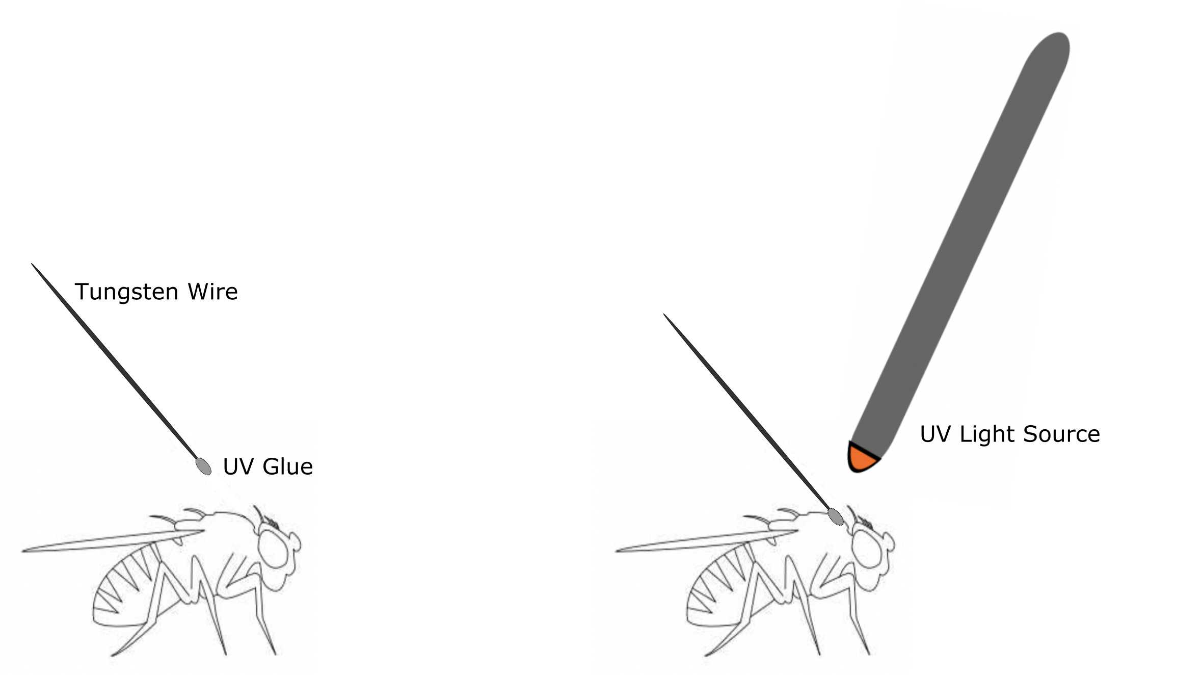
To tether a fly, first prepare your tungsten wire, UV glue, UV glasses, UV light, clay, and flies. Flies should be rendered immobile by placing them on ice for approximately 10 minutes before moving them under a stereoscope for tethering. Place a small drop of UV glue on one end of the tungsten wire and touch this glue to the notum of the fly, close enough to the head to prevent the wire or glue from interfering with flight initiation. Shine your UV light on the glue (for approximately 1-2 seconds) to cure the glue, leaving the fly now connected to the wire. Insert the other end of the tungsten wire into a piece of clay for positioning. Let the flies rest in the dark to get adjusted to the tether for at least 5-10 minutes.
Figure 3: Schematic for tethering flies using UV glue
For each experiment, place a single tethered, dark recovered fly in the center of the stereoscope objective, 2 mm in front of the LED.
Attach a cell phone to the camera mount on the stereoscope using double sided tape. Use the stereoscope to focus the cell phone camera on the fly. To capture video, use your cell phone camera's built in slow motion video feature, or a cell phone app that simulates slow motion video. We recommend the slo-mo application 'SloPro' for iPhones, or 'Slow motion video FX: fast & slow mo editor' for Androids.
Note: These apps simulate high speed video capture.This permits students to recognize the initiation or cessation of evoked behaviors that are quite rapid and difficult to observe by the human eye and not be limited by the highest frame rate of their cell phone camera.
Turn on the Arduino board, and the green Board LED should light up.
After positioning the fly and adjusting the camera, initiate a video recording and a 300ms red light stimulation (measured to be 0.1605 mW/mm2 at the fly’s location) by touching the record button on the phone. Click the record button again to end the video recording which now contains the fly's behavior in response to light stimulation.
The Board LED will turn blue for 30 seconds, and unable to produce another red light pulse in this time, to avoid overstimulation of the flies.
Once the Board LED returns to green, a new fly can be optogenetically activated.
Each fly should be exposed to only one light stimulation and then placed back in a covered box. Both of these actions are to avoid desensitizing their light-sensitive receptors, ensuring their behaviors will be elicited by the red light stimulus.
Tip: For giant fiber (GF) activation experiments, provide experimental and control flies a small piece of a Kimwipe (Kimberly-Clark) to “kick” away during a takeoff to make the escape behavior more obvious.
Annotating Fly Behavior
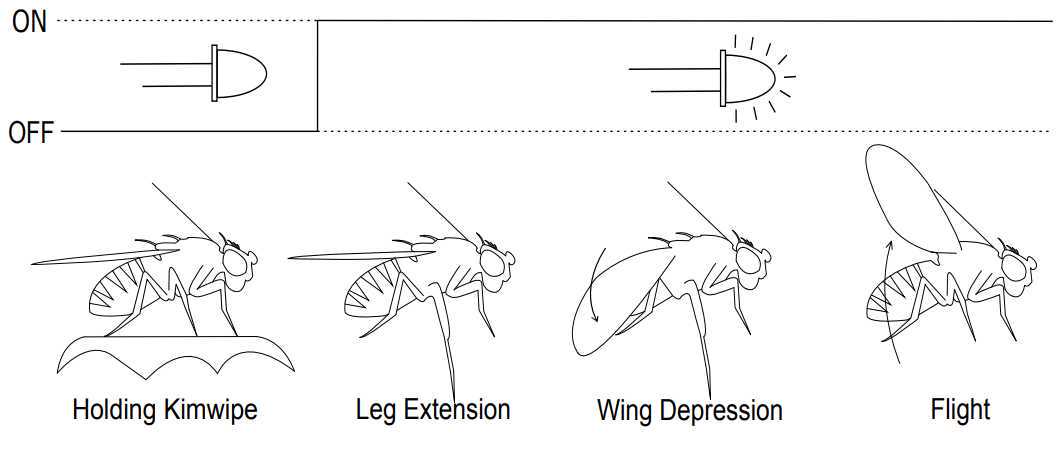
Annotate escape behaviors by replaying the video and determining, after the light turns on, if the fly drops away the Kimwipe piece and performs the following steps: leg extension, wing depression, and flight initiation. A schematic documenting this is shown in Figure 4.
Figure 4: Schematic demonstrating the detectable escape behavior
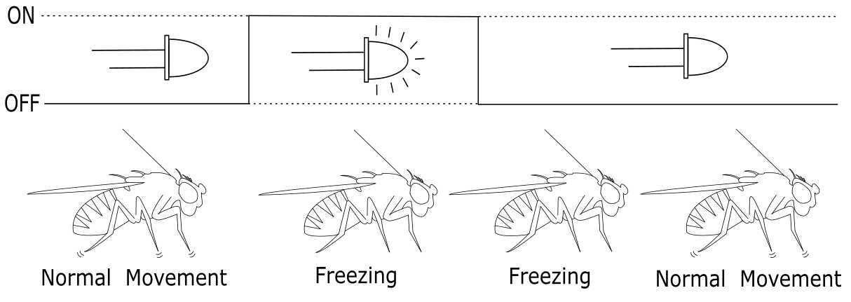
Annotate freezing behaviors by replaying the video and determining, after the light turns on, that the fly makes no movements and remains perfectly still. Freezing behavior is defined as a complete cessation of motion for at least 120 ms. This period of no motion may continue briefly after the light has been shut off. A schematic documenting this is shown in Figure 5.
Figure 5: Schematic demonstrating the detectable freezing behavior
Annotate the absence of an optogenetically induced behavior by determining, after the light turns on, that no escape or freezing behavior occurred. It is possible that control flies may demonstrate a brief (<120ms) freezing response to the red-light stimulus, but this is easily distinguished from a sustained freezing response.
Running the Workshop
To utilize this device in a neuroengineering workshop for high school students, each workshop should take approximately 1.5 hours.
Each workshop should begin with an initial assessment in the form of a short quiz to assess how well the students learned the concepts. The quiz is to ask each student to answer the following four questions with short answers and sketches: (1) “What is a neuron?” (2) “What is a neural circuit?” (3) “What is a sensorimotor transformation?” (4) “What is optogenetics?”
The instructor should then give a short lecture of about 10-15 minutes. The lecture should introduce the fruit fly Drosophila melanogaster and the rationale as to why it is such a valuable model organism for investigations of neuroscience and developing neurotechnologies. Background should include Drosophila takeoff escape and freezing behaviors to explain the concept of sensorimotor transformations and provide an overall reference for Drosophila central nervous system anatomy. Next, the instructor should introduce optogenetics and lead a discussion with the students on how optogenetics can be applied to dissect out neural circuits that underlie sensorimotor transformations. The instructor should then explain the experimental design for the active learning activity incorporating the optogenetics device.
High school students should be divided into groups of 2-3 students and provided a stereoscope, an optogenetics device, and a covered box of tethered flies.
Students should follow the 'Optogenetic Activation' protocol when performing the workshop.
The instructor will reconvene with the students after running the experiment to discuss their results and postulate on how activated cell types may contribute to Drosophila collision avoidance behaviors. The same quiz should be given to the students again, to assess the difference in the students' understanding of these neuroscience concepts before and after the workshop.
All quiz results should be graded using a 4-point scale, with 0 representing no understanding of the concept, 1 representing novice understanding of the concept, 2 representing moderate understanding of the concept, and 3 representing full understanding of the concept.
Drosophila Tethering
The other end of the tungsten wire was inserted into clay for stability and future positioning.
Flies were placed in covered freezer boxes to recover in the darkness for more than five minutes prior to the start of experiments. Flies can be given a small piece of Kimwipe for them to hang on to prior to the start of experiments.
