Fixation and Embedding of Eyes at UAB
Jamie Allen, Jeff Spraggins, Jeffrey D. Messinger, David Anderson, Christine A. Curcio, Melissa Farrow, Kevin Schey, Angela Kruse
Abstract
The accession and fixation of whole human eye specimens at University of Alabama Birmingham as part of the Human Biomolecular Atlas Project.
Steps
Collection, dissection, and preservation of ocular tissue
Whole donor globes on wet ice were received within less than 6 hours time of death (TOD) from the Advancing Sight Network (500 Robert Jemison Rd Birmingham, AL 35209). Laterality was verified using extra ocular anatomy.
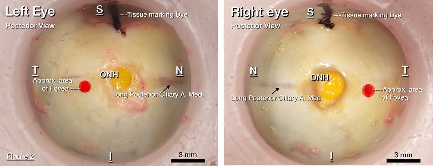
Tissue orientation was preserved using tissue marking dyes in (Cancer Diagnostics Inc. Durham, NC) black, red, and, yellow identifying the superior rectus muscle, fovea, and optic nerve head respectively.

To facilitate removal of the cornea and preservative penetration, a circular cut was scored through the Ora Serrata using an 18-mm trephine (Stratis Healthcare, #6718L) and a small 3 x 5 mm rectangular window incision was made at the scleral-cornea junction by first making a small (~5mm) incision with a scalpel or similar, then completing a rectangular incision area with curved spring scissors (Roboz Cat# RS-5681).

The globe with incisions described in step 3 is immersed in immersed in ice-cold 4% paraformaldehyde (EMS Cat#15713-S) in Sorenson’s Phosphate Buffer, 0.1M pH 7.2 (EMS Cat# 11600-10) and allowed to fix for 24 hours at 4°C.
After 24 hours, the anterior portion was removed using the trephine-scored incision described in step 3.
Color fundus photography
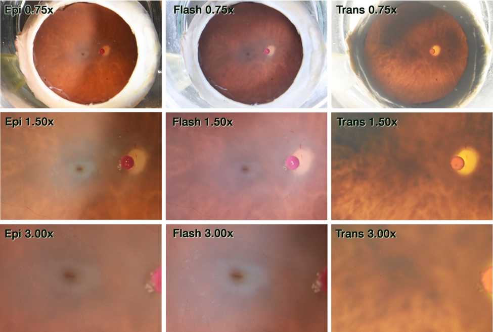
After 24 hours, globes are placed within a 30 cc quartz crucible (Fisher Scientific # 08-074D) in correct anatomical orientation (aka facing the patient). Size was referenced using a 1 mm diameter ruby bead (Meller Optics Cat# MRB10MD). Color fundus photographs were obtained using a Nikon D7200 DSLR camera mounted to an Olympus SZX9 stereo microscope at 3 magnifications (0.75x, 1.50x, and 3.00x) with 3 modalities of epi, flash, and trans illuminations.

Optical coherence tomography (OCT)
Optical coherence tomography (OCT) images of globes were collected using a Spectralis Spectral Domain OCT (HRA&OCT, HRA2; Heidelberg Engineering) as follows:
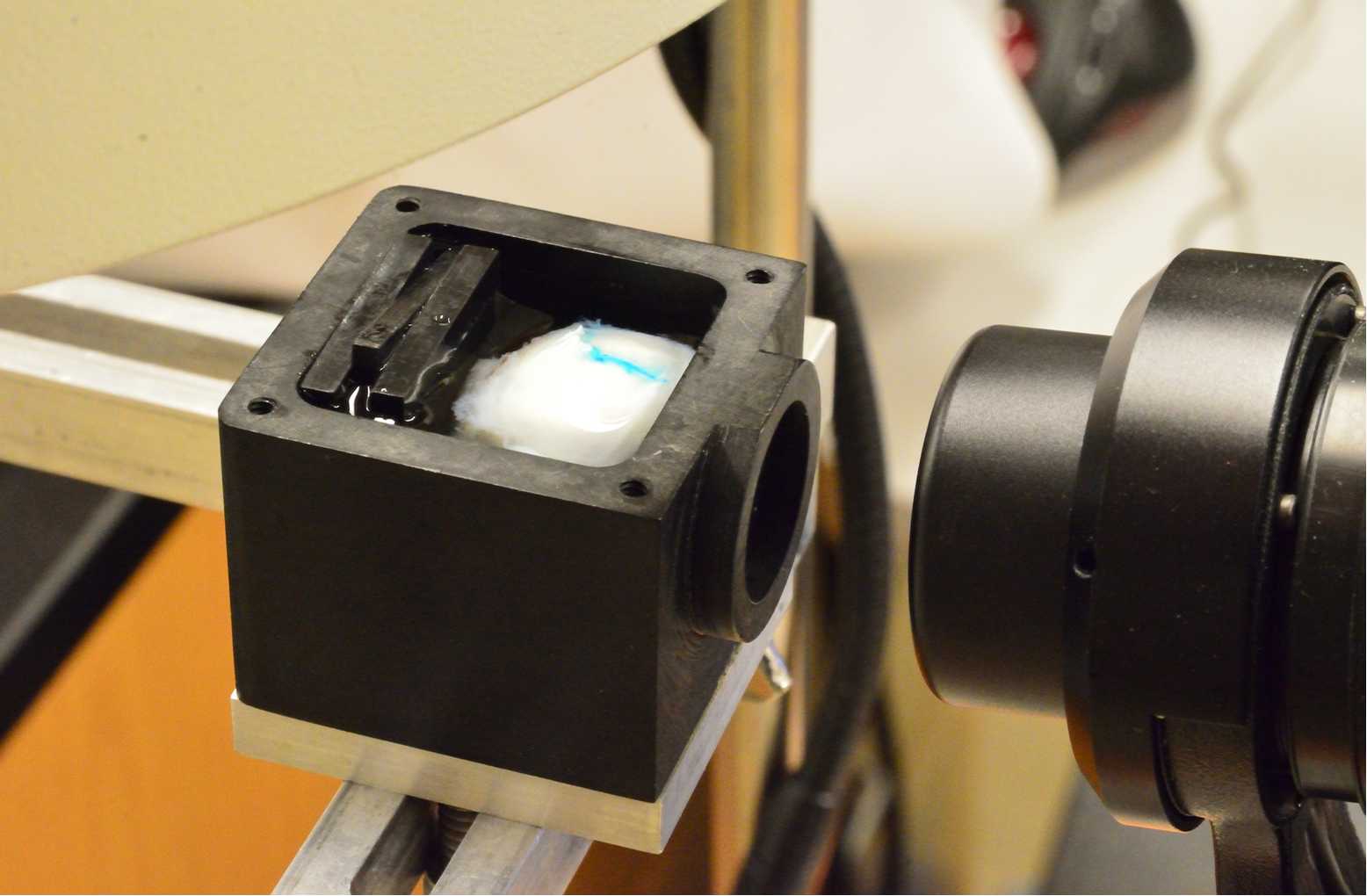
Globes are immersed in chilled Sorenson's buffer with the anterior orientation facing the objective lens of the OCT device within a custom-built chamber with a 60-diopter lens (Pang et al., 2015)

Spectral domain OCT was acquired with the following parameters:
30° macula cube
30 μm spacing
Automatic Real-time averaging ≥50
Near-infrared reflectance, red-free reflectance, and autofluorescence (488 nm excitation wavelength) modalities
Tissue orientation and embedding
Orient the posterior portion of the eye in a cryomold (Peel-A-Way 22 x 30 mm molds, Polysciences # 18646B) with the assistance of a stereo microscope (Nikon SMZ 1000 or similar), as follows:
Using a razor blade or similar, carefully remove the bottom of one cryomold. Place within a second cryomold to create a double-stack.
Label double-stacked cryomolds corresponding to the tissue orientation denoted by the tissue marking dyes.
Prefill the bottom of the mold with 5 ml of 15% fish gelatin.
Place the superior pole (black tissue mark) along the mold side with the fundus facing directly upwards.
The optic nerve head (ONH) and fovea (yellow and red tissue marks, respectively) are placed on the bottom of the mold. Label the bottom of the mold with their locations.

With the tissue oriented as in step 7.
Allow gelatin to semi-freeze by holding the mold suspended in liquid nitrogen until semi-solid and tacky to ensure stable positioning of the posterior pole in the cryomold. Use forceps to suspend mold within liquid nitrogen in dewar.
Slowly fill the fundus first with 15% fish gelatin and allow the fish gelatin to overflow out of the fundus cup until the entire mold is filled
Freeze the mold and tissue with liquid nitrogen, but do not let liquid nitrogen flow over the top of the mold.
Store in a -80oC freezer in a Bitran Freezer Bag (Fisher Science cat# 19240150) until shipment.
Label one additional cryomold for anterior portion (removed in step 4), indicating the location of the superior pole (black tissue marking dye). Optionally, draw the shape of the cornea on the side of the mold.
Prefill the mold with 5 ml of 15% fish gelatin.
Place anterior pole in mold with the cornea facing down.
Allow gelatin to semi-freeze until semi-solid and tacky in liquid nitrogen to ensure tissue adherence. Use forceps to suspend mold within liquid nitrogen in dewar.
Completely fill mold with 15% fish gelatin.
Freeze entire mold with liquid nitrogen, but do not let liquid nitrogen flow over the top of the mold.
Store in a -80oC freezer in a Bitran Freezer Bag (Fisher Science cat# 19240150) for shipment to Vanderbilt University.

