C. elegans worm size measurement
Laura Breimann
Abstract
Protocol to detect the size (length + width) of worms using a stereoscope and a camera.
The protocol was used in the publication:
Steps
Preparing worms for imaging
Select worm line(s) and prepare the worms for size measurement.
For the synchronizing-by-picking method, pick (at least) 20 gravid Adult worms and place them on a fresh OP50 plate. Allow worms to lay eggs for 4 hours and then remove Adults from plates.
Grow worms to the desired stage.
Wash worms off the plate using M9. To remove all bacteria, let worms settle in a tube for 10 min and carefully replace the M9 with fresh M9. Repeat this step 3 times. After the last step, remove most M9 from the tube, leaving only 20 µl with the worms.
To get a clear picture of the worms, lightly anesthetize the worms by adding 10 mM Levamisol to the tube. Wait 5 minutes and gently pipette worms onto an unseeded agar plate.
Separate the worms from each other using an eyelash pick. The goal is to have evenly spread worms that are not touching and are not too close to the wall.
Imaging worms
To capture images of the worms, an eyepiece camera (for example the Dino-Eye camera) can be used. It is also possible to capture images using a phone with an adapter. Phone adapters can be 3D printed with many available designs online. Importantly, keep the zoom of the camera and the microscope constant for one experiment. Try not to image worms twice. If the camera allows it save raw file formats otherwise use the camera format that is available.
Equipment
| Value | Label |
|---|---|
| AM4025X Dino-Eye Edge Eyepiece Camera | NAME |
| Eyepiece Camera | TYPE |
| Dino-Lite | BRAND |
| AM4025X | SKU |
Use a microscope calibration ruler and take an image with the same settings. This will allow you later to give the results a unit.
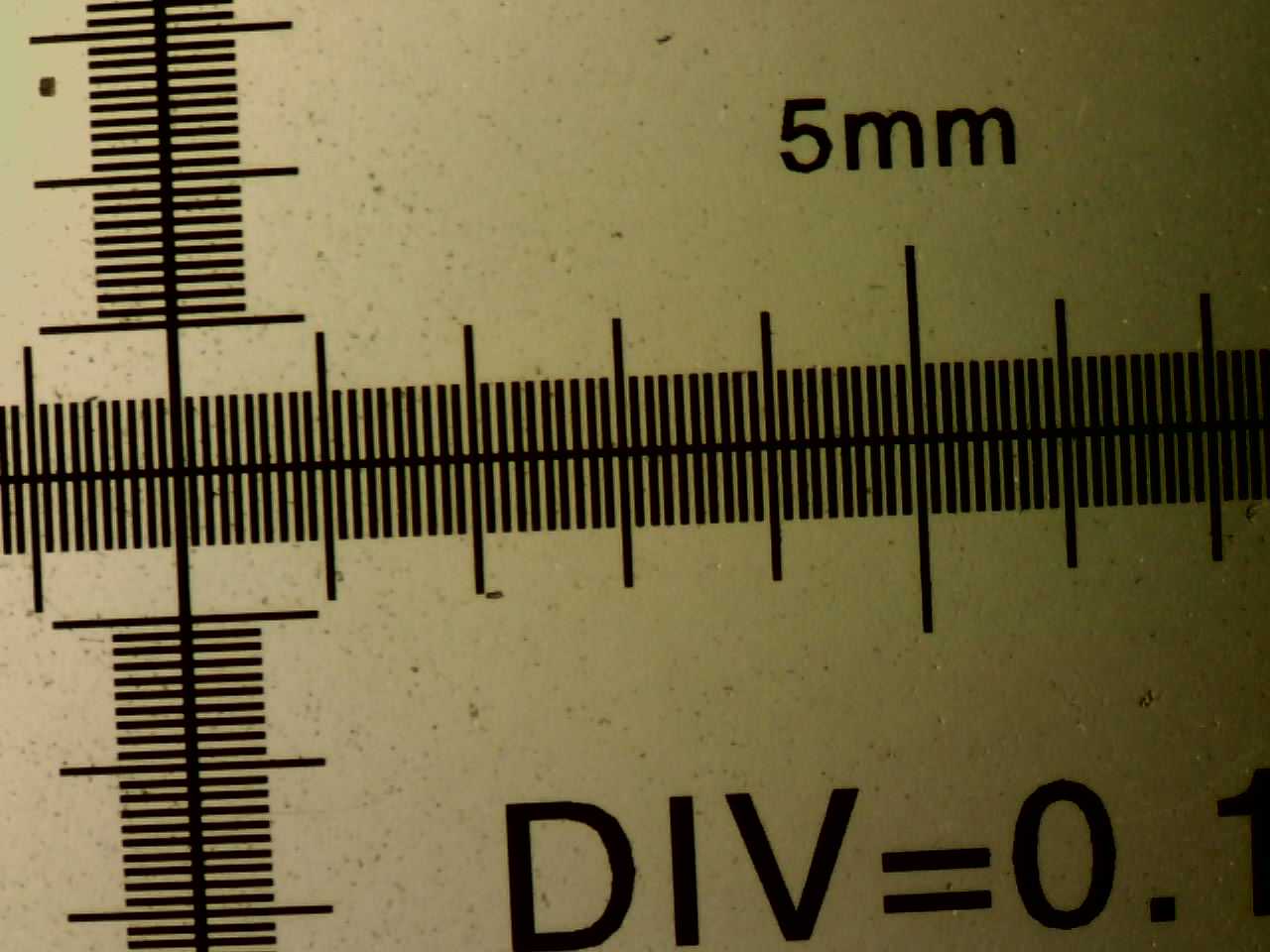
Microscope calibration rulers can be found here.
Preparing images for analysis
Save images for one condition in a folder.
Use Fiji to open the images and remove background.
Software
| Value | Label |
|---|---|
| FIJI (FIJI Is Just ImageJ) | NAME |
| https://imagej.net/Fiji/Downloads | LINK |
-
Open image using Fiji
-
Set the image to 8-bit: Image > Type > 8-bit
-
Subtract background: Process -> Subtract Background. Set the preview checkbox to see how changing rolling ball radius changes the results.
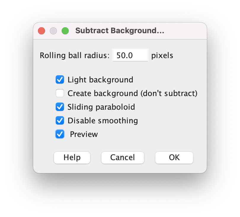
-
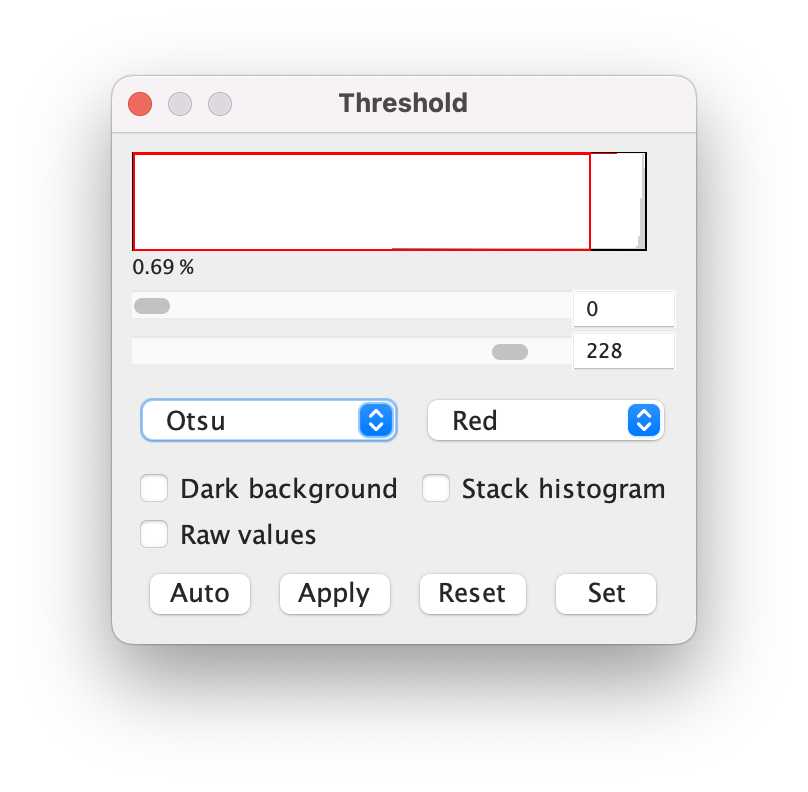
Threshold: Image -> Adjust -> Threshold; where it says “Default”, change it to “Otsu”. Move the sliding bars so that you get as much of the worms highlighted, and as little of the background. Then click “Apply”.
- Save the image to a new folder for further analysis.
To run the above code on many images, you can use this Fiji macro. Make sure to adapt the parameters in the script after finding them manually.
To get the resolution of your measurements, open the image of the calibration ruler.
-
Use the line tool in Fiji

-
Draw a line between two known points on your ruler (for instance a millimetre)
-
Press command + M to open a results Window with the measurements to give you the length in pixels.

-
For “Microns per Pixel”, divide the number of microns your line is (In our case it was a mm, so it would be 1000 microns), by the length of the line in pixels from the step above.
-
Write down this number for the next step
Alternatively, read here for more instructions.
Measuring worm size
Download the WormSizer plugin through the Fiji plugin menu. In Fiji navigate to "Help" > "Update" > "Manage Update Sites" and select "WormSizer" in the list of plugins and click "Close" and "Apply changes". After restarting Fiji, the plugin can be found in the Plugin drop-down menu.
More info on how to use the plugin can be found here.
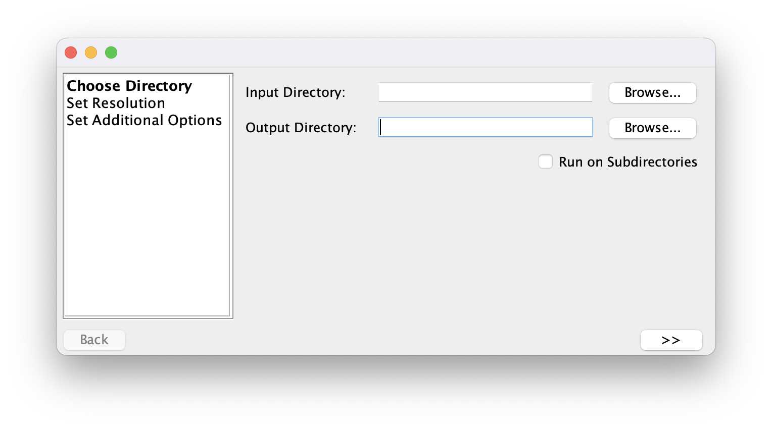
Select an input directory including your pictures and an output directory to save the results. Click the >> button to continue.
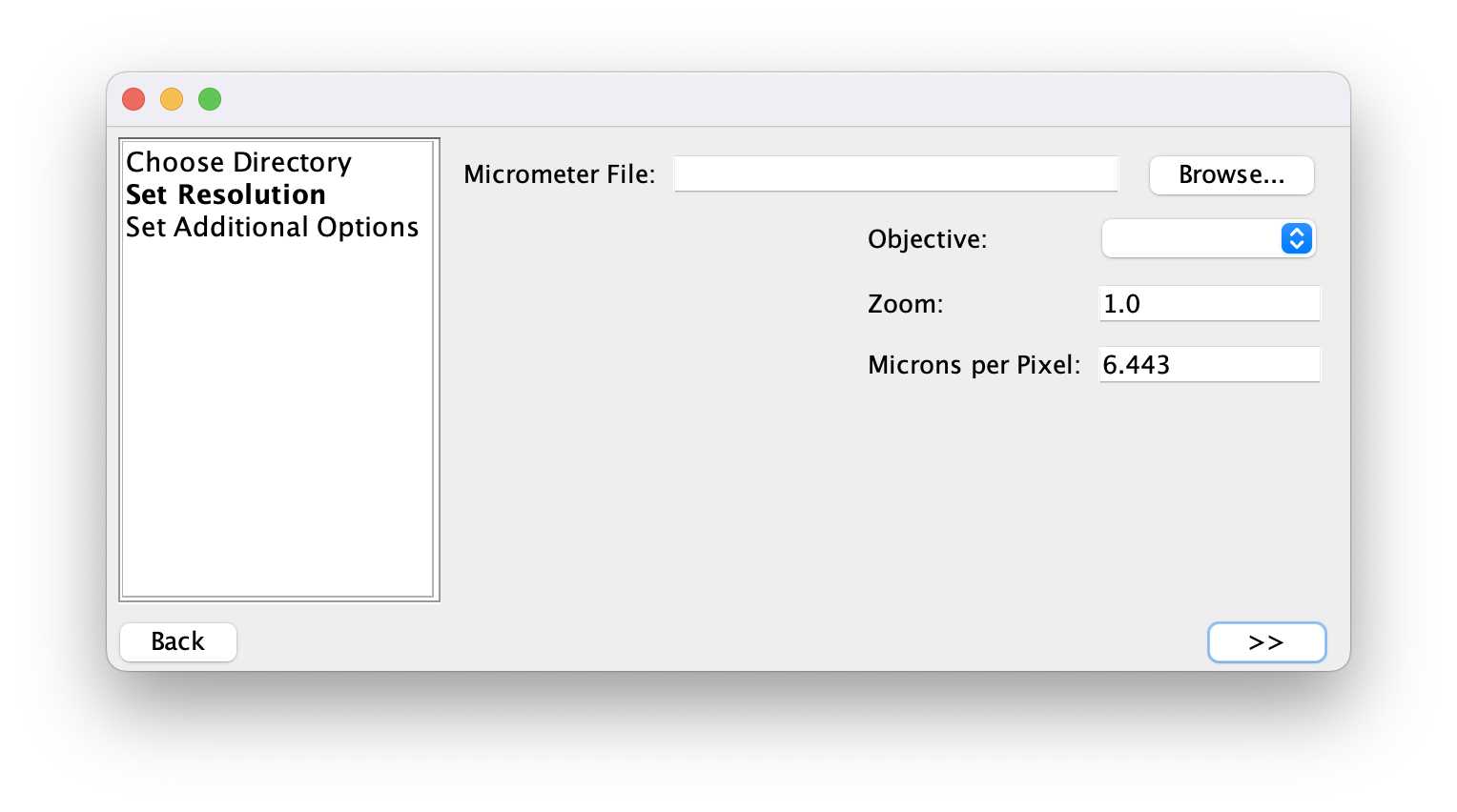
Set the length in microns that were measured for the calibration ruler. Click the >> button to continue (this can take a moment depending on the number of images in the folder).
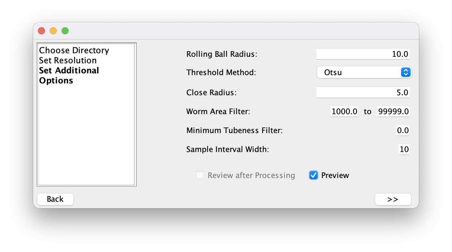
Next, select the settings to find the worm outlines. Depending on the images and the magnification they will be different. After the selection, pressing the >> button will start the detection in all images in the folder.
The processing complete image will signal when the plugin detected all worms and the review can start.
The plugin produced three files in the output folder:
- settings .csv file
- experiment .xml file
- results csv file
The settings file saves the settings selected for detection. The XML file saves the outline information about each worm and can be used to review the outlines. The results file contains the worm measurements for each detected worm.

Reviewing the detections is done using the magnifying symbol. Navigate to the output folder and select the .xml file.

In the review part of the plugin, you can go through all detected worms in all images and select whether you want them to be included in the downstream analysis.


The results file is updated while reviewing and changes the value in the "pass" column to either TRUE or FALSE.
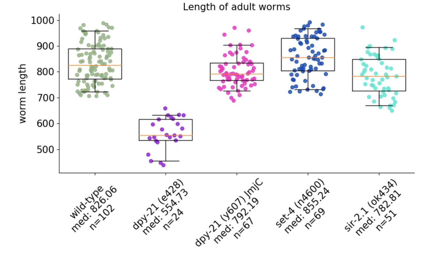
Plotting results
The results file can be used to plot the results. An example script using Python can be found in this GitHub repository.