Assembly: Chronic recoverable Neuropixels in mice
Emily A Aery Jones
Abstract
This protocol collection explains how to build a low-cost, lightweight system to implant 1 Neuropixels 1.0 probe or 2 Neuropixels 2.0 probes into mice, record during freely moving behavior, then recover the probes for future use. This protocol explains how to 3D print components, sharpen, solder, and test the probe, and prepare components for surgery. See full collection for more details.
Before start
If your probes do not have a metal cap, you can 3D print or machine the file provided at https://github.com/emilyasterjones/chronic_NPX_mouse/tree/main/probe_holders (or https://github.com/emilyasterjones/chronic_NPX_mouse/tree/main/2.0_probes for 2.0 probes). To attach the cap, secure the probe in the modeling clay, apply superglue to dovetail cap, position, press together for 0h 0m 30s , and allow to cure .* The grindstone only accepts thin metal rods, not those compatible with stereotaxes. Machine a compatible rod using the file provided at https://github.com/emilyasterjones/chronic_NPX_mouse/tree/main/probe_holders.
Steps
3D print components
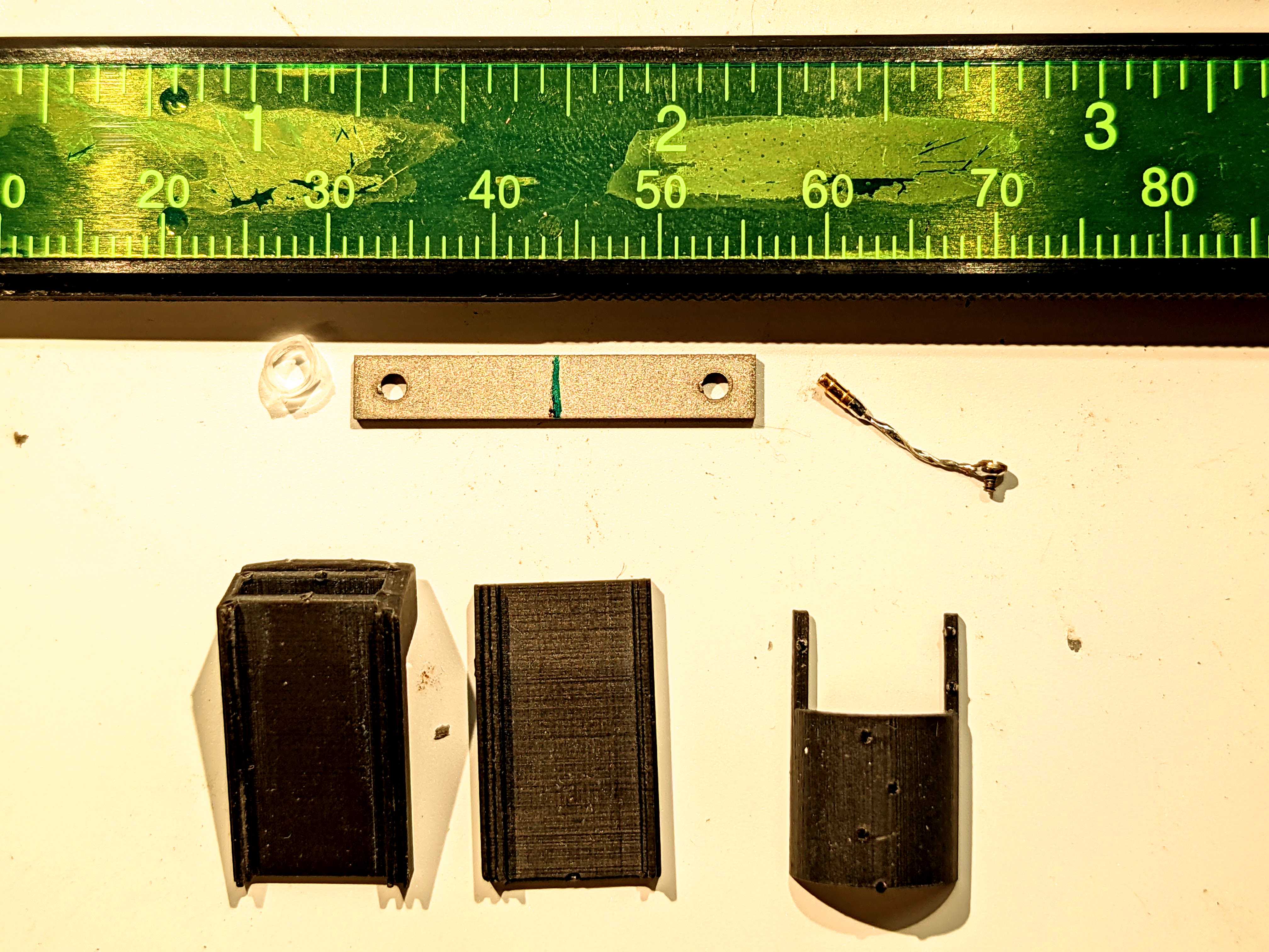
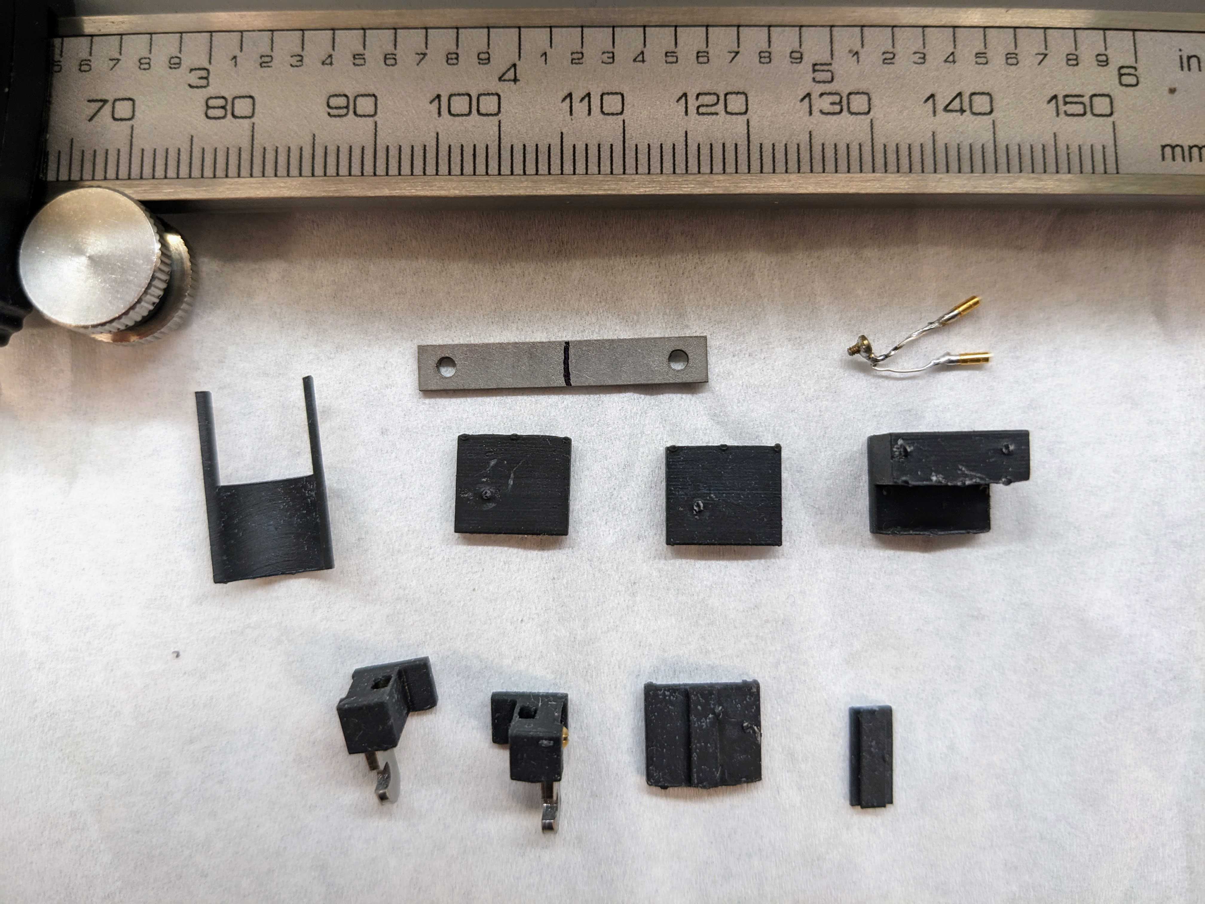
Single 1.0 probe: Build a print file for the following pieces per mouse: 1 each of body piece, back and front flex cable holders, and dome, plus 2 wings.
Dual 2.0 probes: Build a print file for the following pieces per mouse: 1 each of left body, right body, flex holder 1, flex holder 2 with dovetail, and dome, plus 2 flex holder 2s. For beta 2.0 probes also print a dovetail.
To re-use explanted probes, print everything except for the pieces permanently affixed to the probe. Print 1 headstage holder per recording rig. Files located at https://github.com/emilyasterjones/chronic_NPX_mouse.
Place all build files into a single print file. Orient each component so it is well-supported, with supports attaching to non-interface points. These are: rounded hooks of wings, top of body piece (where hex nut slot is), flat backs of flex cable holders and headstage holder, and any side of dome. See single_mouse_print.form file for example using Formlabs system.
Print the file.
Remove prints from the build platform. Remove liquid resin from prints and cure according to manufacturer instructions for your printer and resin.
Remove supports with wire cutters for fine surfaces & twisting print & raft apart for larger surfaces.
Machine components
Machine 1 headbar per mouse from stainless steel or titanium.
Dual 2.0 probes: machine 2 wings per mouse from stainless steel or titanium.
Build probe box
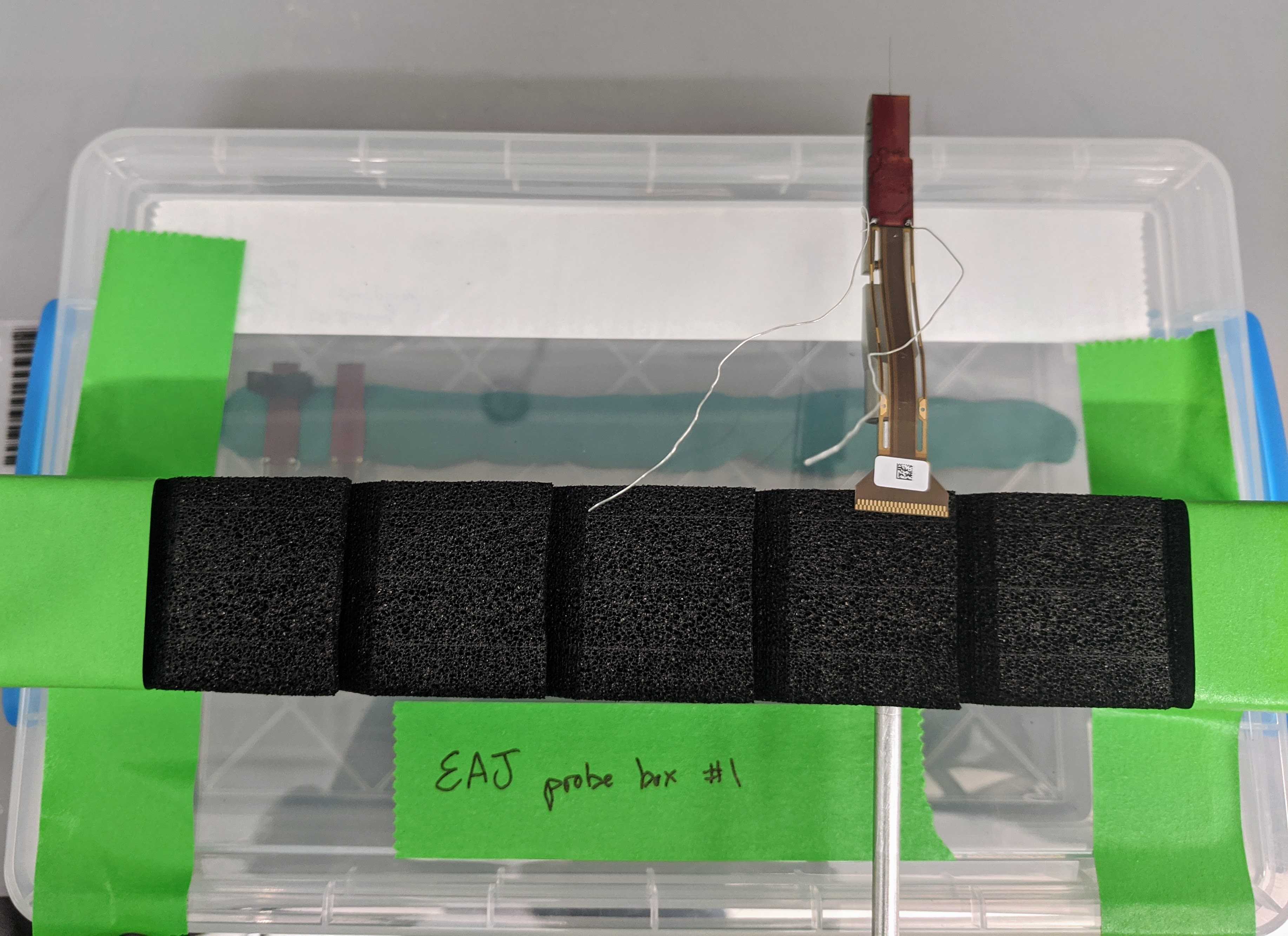
Along the base inside the plastic case, place a thick (>1cm) piece of modeling clay in a ~3cm strip about one-quarter of the way from the top of the box. The clay should be thick enough so that you can press a probe into it without worrying about the shank hitting the box and wide enough to securely hold the PCB board of the probe.
From an empty probe box, remove the foam interior. Cut the probe holding foam strip out of this. Tape this strip to the top of the box. This will grip any metal rod attached to the Sensapex holder to secure the probe during soldering, gluing, or waiting to be mounted to the stereotax or clamp.
Sharpen the probe
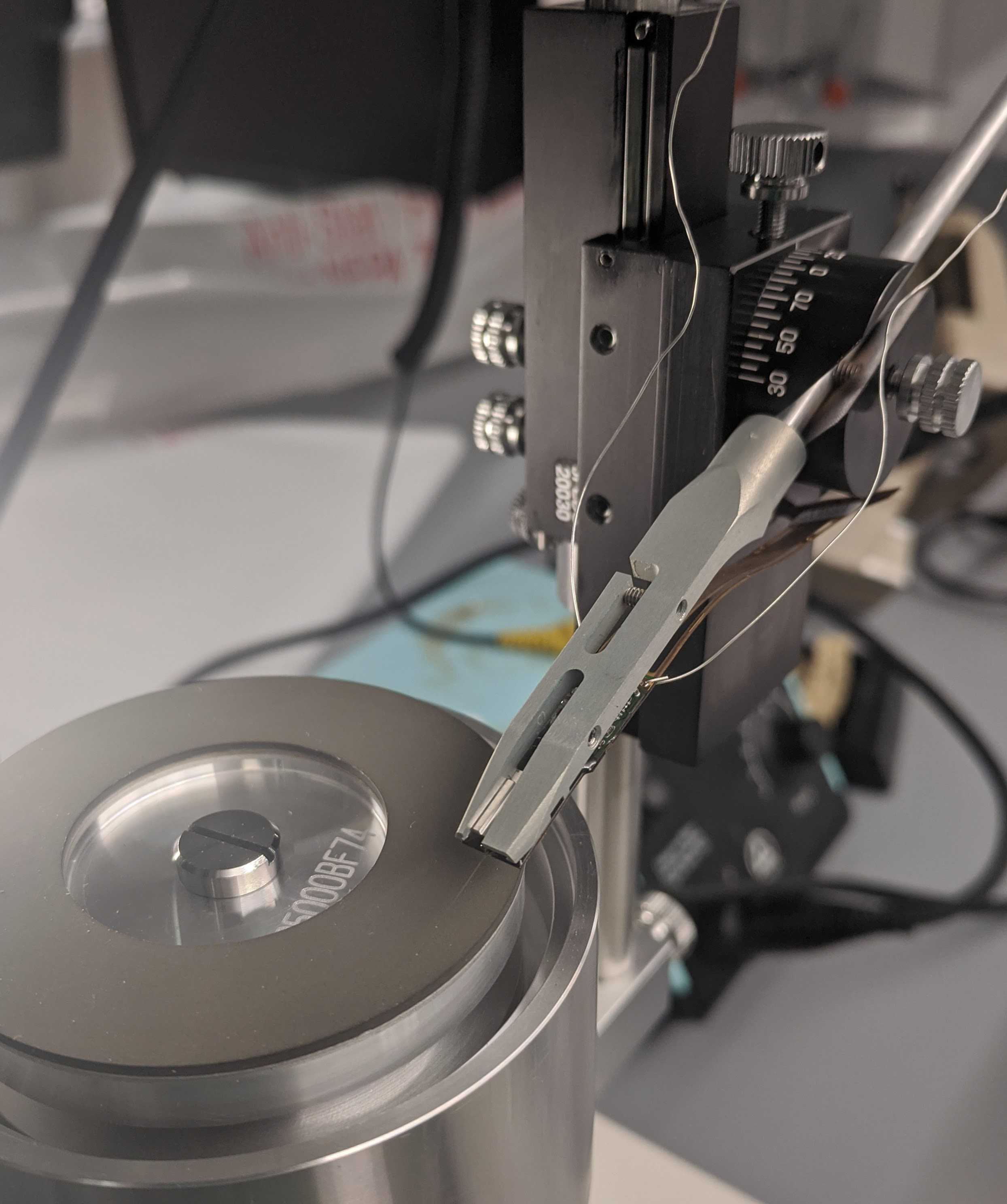
Load the probe into the Sensapex holder. Screw the holder into the thin metal rod.
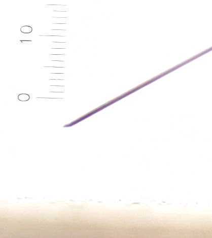
Sharpening probes can improve cell yield and allow you to puncture dura without removing it. Sharpen probe according to this protocol: https://github.com/cortex-lab/neuropixels/wiki/Sharpening
Solder probe and ground screw
Thread silver wire between the ground and reference pads on the back of the PCB board, then down to a few mm below the PCB. Solder. Keep the iron cool (~315C/600F) and don’t heat for longer than 4s. Optional: trim the ground and reference pad flexes above the PCB board as these aren't necessary.
Solder gold male pin to the end of wire.
Apply flux just under the head of the ground screw. Wrap a loop of wire around this & twist to tighten. Solder closed.
2.0 probes: Solder a second loop of wire around the ground screw for the second probe.
Solder gold female pin to the end of this wire.
Test signal
Mount the probe in a clamp or micromanipulator and submerge shank into saline. Clip the ground wire into the saline on the side of the beaker.
Plug in the headstage. Run BIST tests. Observe the signal and noise level on SpikeGLX to confirm your soldering is good and the probe is functional.
Assemble
Add nuts into slots on body piece. Apply a little superglue to the bottom edge of the nut before inserting, then allow to cure for 5 minutes. Attach wings and screw to affix.
1.0 probes: Superglue the back of the probe to the 3D printed body piece. The wings extend 6mm beyond the body piece and you'll need some room for dental cement, so set the piece at [your target depth]-3mm away from the base of the shank.
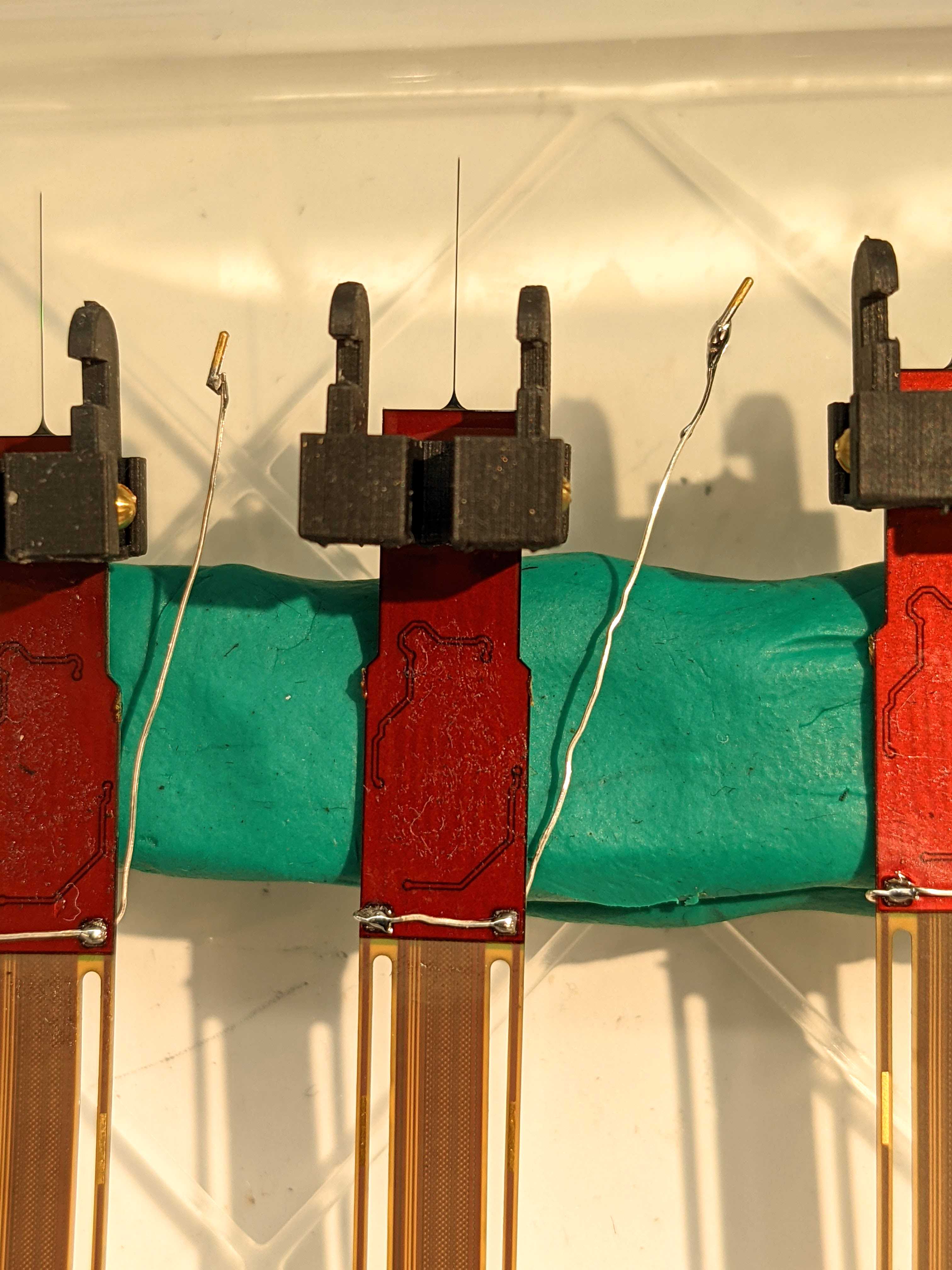
2.0 probes: Superglue the front (green side) of the first probe to the right body piece. This will be your anterior probe. Superglue the back (brown side) of the second probe to the left body piece. This will be your posterior probe. Position so that the body pieces are at the top of the metal cap and interior edge aligned with the edge of the probe.
Press together for 0h 0m 30s . Allow to cure .
2.0 probes: Superglue a flex holder 2 with dovetail to the front of the first probe, just above the body piece. For beta probes, also superglue a 3D printed dovetail to the front of the second probe. These 3D printed dovetail substitutes will be used to insert the probes during surgery.
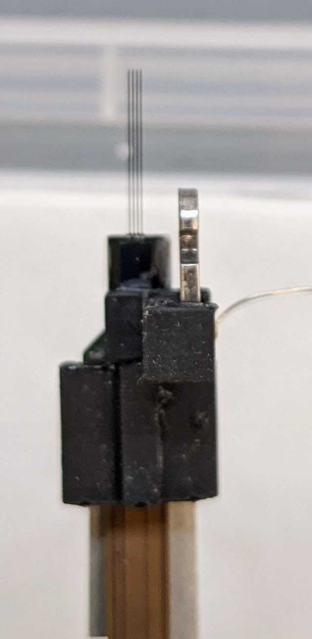
Press together for 0h 0m 30s . Allow to cure .
Mark the center of each headplate (1" long) with a lab marker.
Slice the pipette tips into 1mm diameter, 0.5mm tall circles to create wells for the craniotomy.
Build the headstage holder
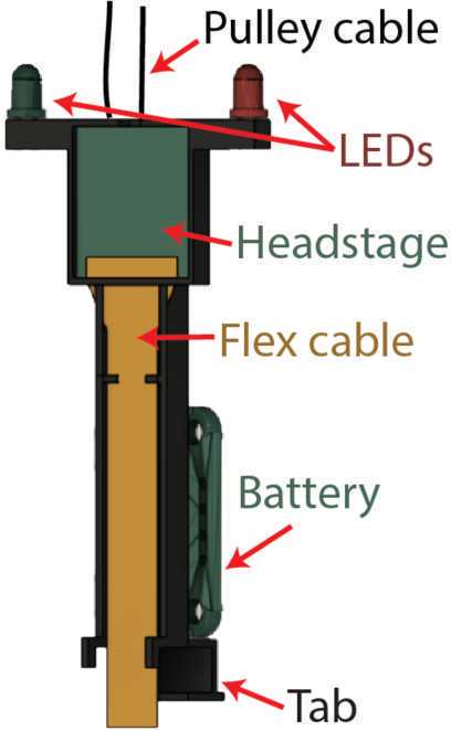
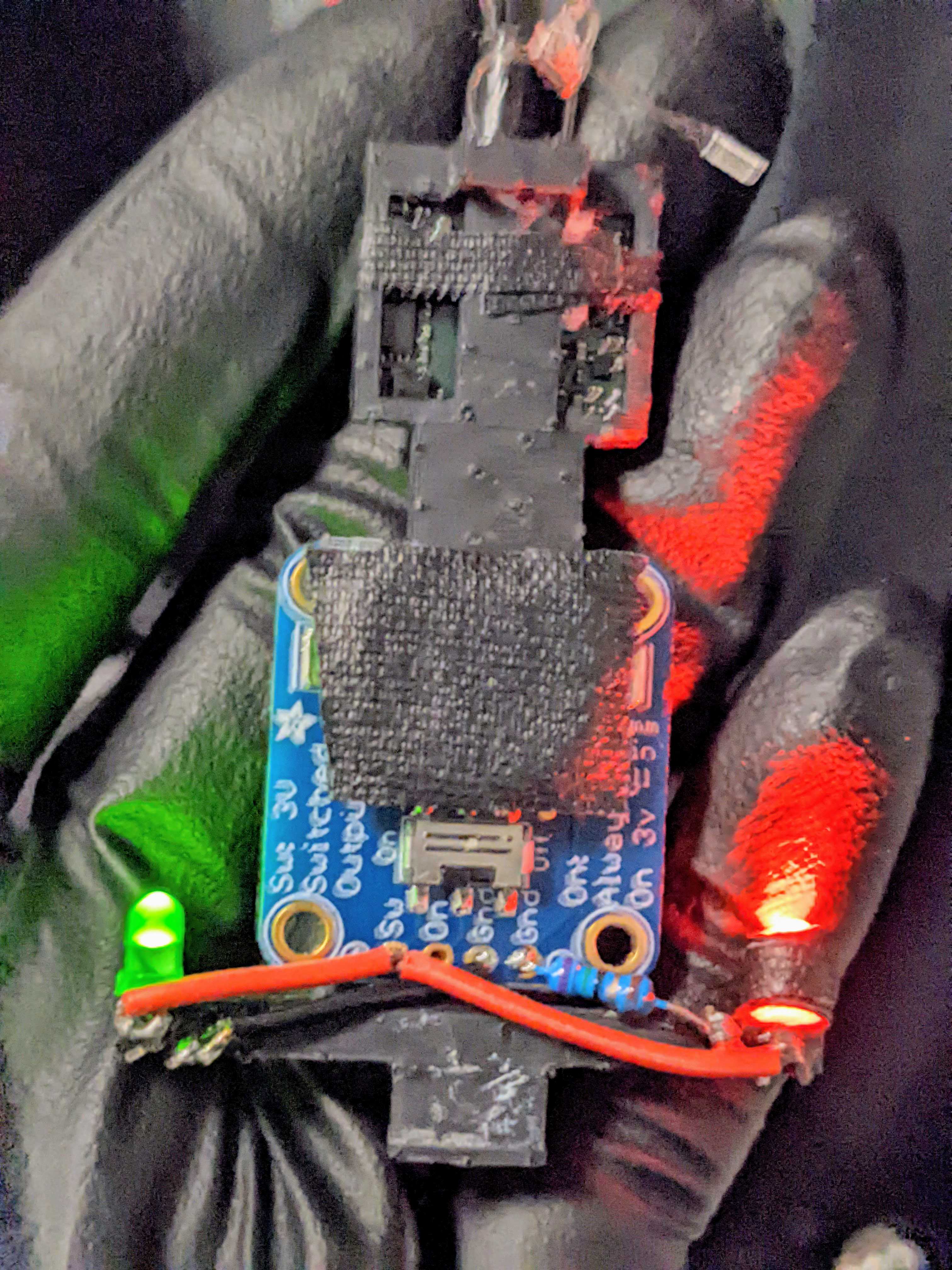
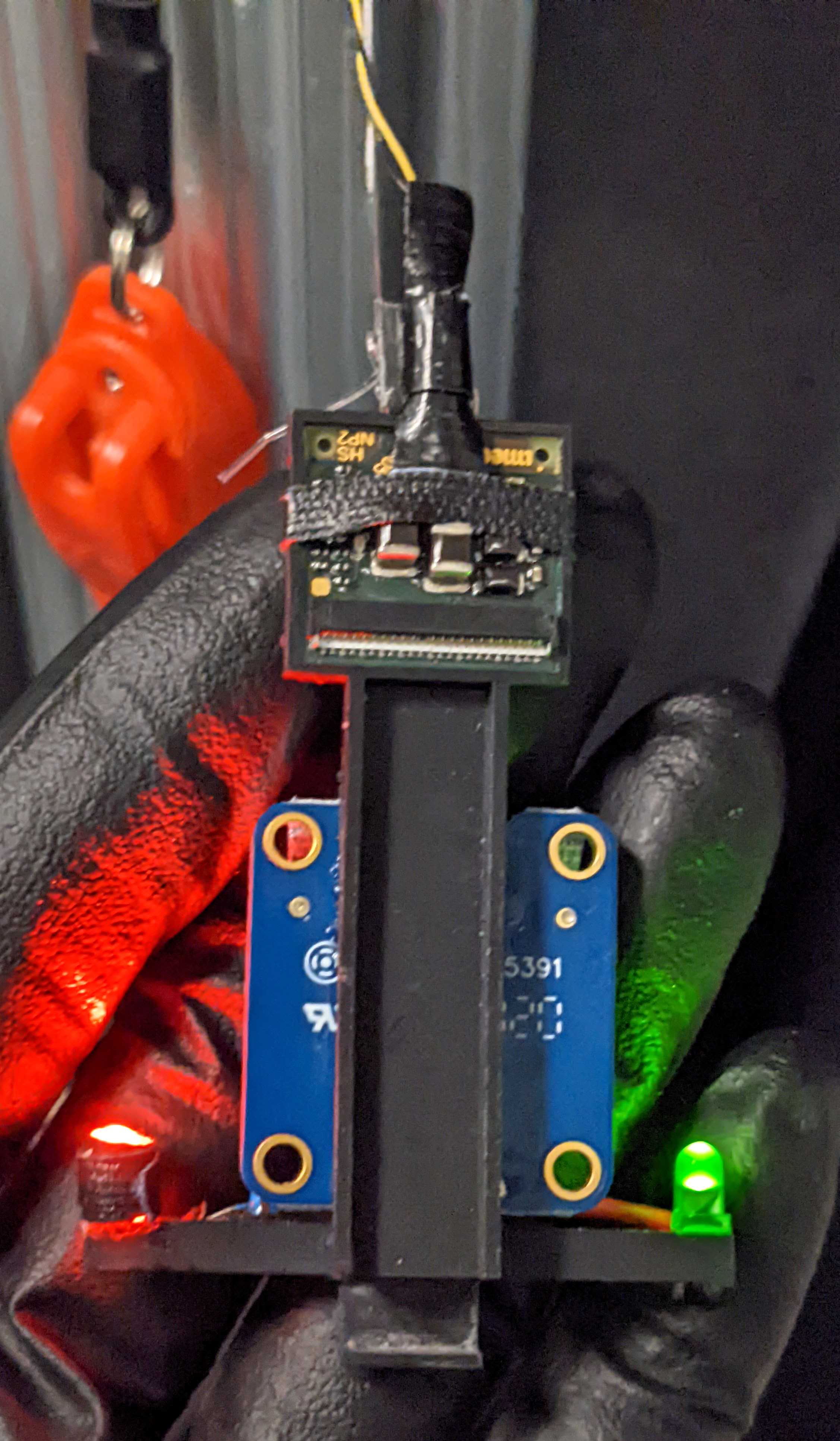
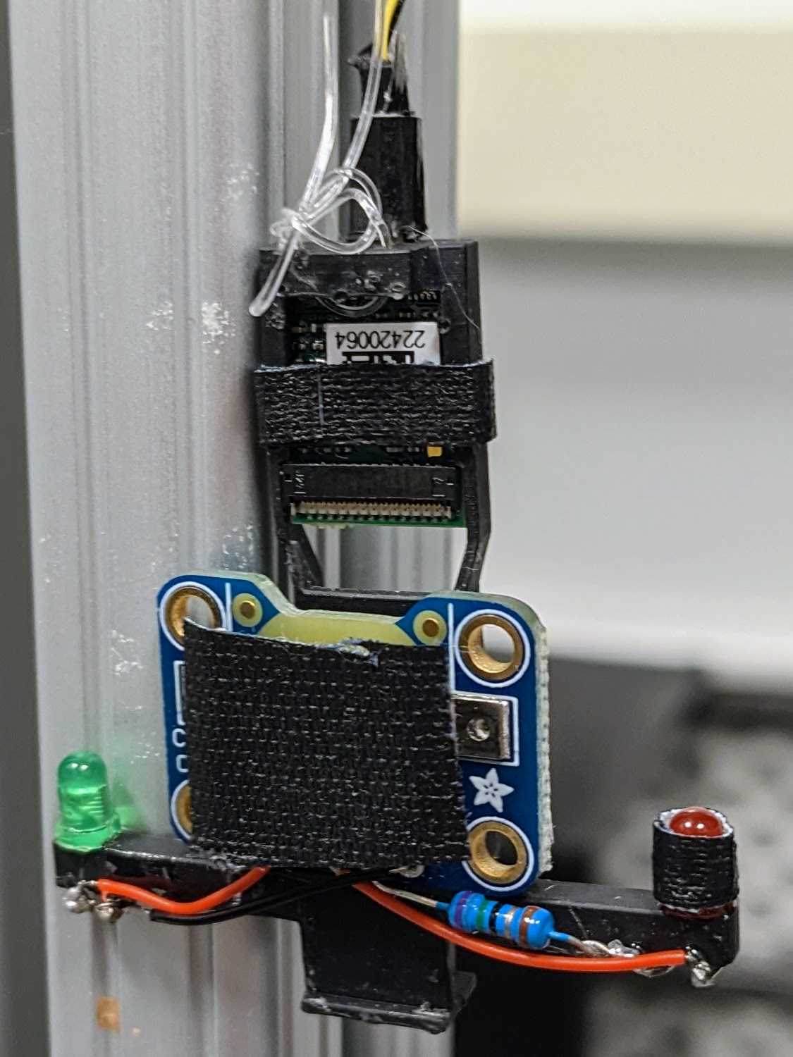
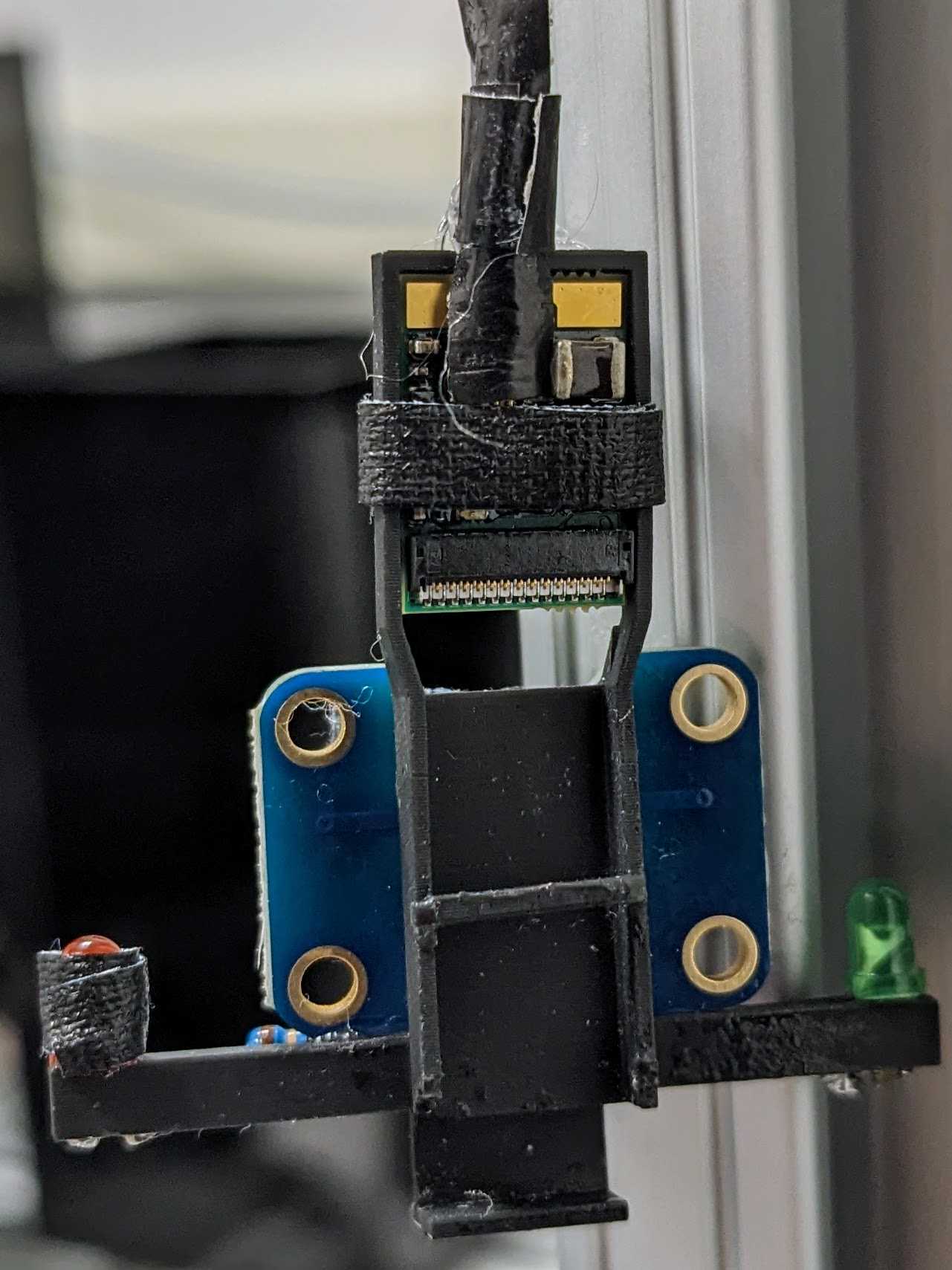
Insert the LEDs through the ends of the headstage holder arms. Wire: LED short lead => resistor => ground, LED long lead => switched power. Insert a coin cell battery and flip the switch to check the connection.
Cover any exposed wire with epoxy. Epoxy the battery breakout to the back of the headstage holder. Mount headstage into slot and optionally secure with tape. Plug into Omnetics connector and secure this connection with tape (this connection easily comes loose).
