Creating Custom Brain Slicing Matrices with 3D Printers
Yosuke Yamazaki, Maki Yuguchi, Keitaro Isokawa
Disclaimer
The protocols.io team notes that research involving animals must be conducted according to internationally-accepted standards and should always have prior approval from an Institutional Ethics Committee or Board.
Abstract
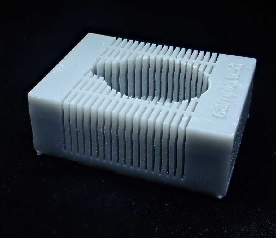
To create reproducible brain sections, brain slicing matrices are often utilized. These matrices are designed with anatomically proportioned cavity dimensions and precisely spaced slice channels, enabling consistent and accurate slicing of the brain into coronal or sagittal sections. Brain matrices can be customized for various animal species or developmental stages, and a wide range of models are commercially available. However, there are certain limitations to the variety of these prefabricated products. In this protocol, we design a brain matrix specifically for rodents, tailored to the measurements of the brain sample, and produce the customized brain slicing matrix with a 3D printer.
Steps
Mesuratent of the sample
The mouse brain sample is placed on the dissection mat.
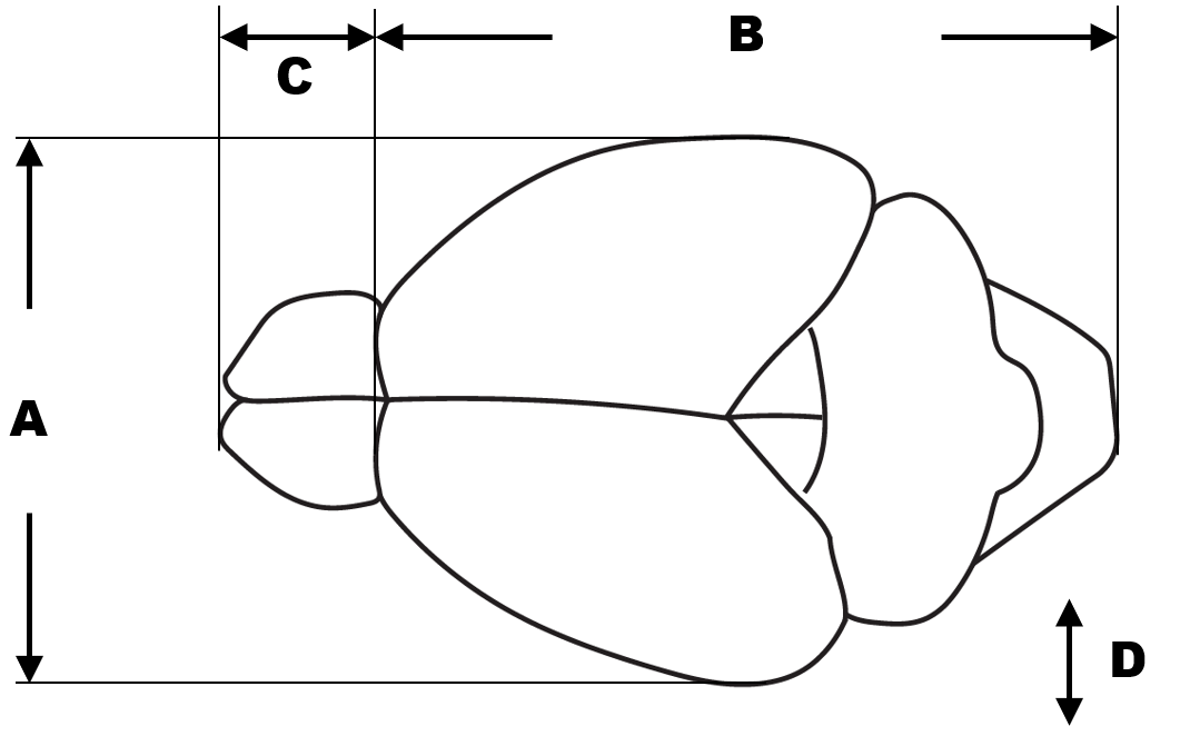
Following the specified metrics, the approximate length is measured.

Installation of OpenSCAD
For Windows, download the installer from https://openscad.org/ and execute the .exe file to proceed with the installation, or use the following command in the terminal:
winget install --id OpenSCAD.OpenSCAD
For macOS, download the dmg file from https://openscad.org/ and install OpenSCAD program from it, or, on a system with Homebrew enabled, use the following command in the terminal:
brew install openscad
Excute the code for generation
Run the OpenSCAD program.
Choose New button for a new file creation.
<img src="https://static.yanyin.tech/literature_test/protocol_io_true/protocols.io.261ge563jg47/q6x45r961.png" alt="Initial screen of OpenSCAD. Start by pressing the "New" button on the left side." loading="lazy" title="Initial screen of OpenSCAD. Start by pressing the "New" button on the left side."/>
Copy and paste the code below to the Editor pane on the left side of OpenSCAD window.
/* [Variables (All units are in mm)] */
// Slice Direction
direction = "coronal"; // [coronal,sagittal]
// Slice Thickness (default=1.0)
thickness = 1;//0.1
// [A] Width of Cerebrum
width = 12;//0.1
// [B] Length from Cerebrum to Cut End of Spinal Cord
length = 15.5;
// [C] Length of Olfactory Bulb
bulb = 4.5;
// [D] Height of Brain (Depth of Matrix)
depth = 7;//0.1
// Width of Slot for Inserting Razor Blade (default = 0.4)
slot_width = 0.4;
// Shift Cutting Position Anteriorly. Active when Coronal is Selected (Numbers Less Than the Value of thickness)
shift = 0;//0.1
/* [Stabilizer] */
// Bridging that connects slots for fabrication stability
stabilizer = "off";// [off,on]
// default = 0.2 (mm)
bridge_diameter = 0.2;
/* [Decolation] */
emboss_text = "no";// [no,yes]
// Text to be Embossed on Top Surface
text_to_emboss = "Your Text Here";
// Font Size of Text (default = 2)
font_size = 2;//0.1
// Calculating dimensions for the outer box
outer_length = length + bulb + 8;
outer_width = width + 8;
outer_height = depth + 3;

module makeOuterbox(){
    cube([outer_length, outer_width, outer_height], center=true);
}

module drawBrainOutline() {
        translate([bulb/4, 0, outer_height/2 - depth/2]) {
            scale([length/width, 1, 1]) cylinder(h=depth, r=width/2, $fn=100, center=true);
            translate([-length/2 + bulb/2, 0, 0]) cube([bulb, bulb, depth], center=true);
            translate([-length/2, 0, 0]) cylinder(h=depth, r=bulb/2, $fn=100, center=true);
    }
}

module makeSlot() {
    if (direction == "coronal") {
        translate([bulb/4, 0, outer_height/2 - depth/2]) {
            for (x = [-(length+bulb)/2 - shift: thickness : length/2]) {
                translate([x, 0, 0])
                    cube([slot_width, outer_width, depth + 3], center=true);
            }
        }
    }
    else if (direction == "sagittal") {
        translate([0, 0, outer_height - depth - 1]) cube([outer_length, slot_width, depth + 3], center=true); // Center groove
        for (i = [0 : thickness : floor(width/2)]) {
            translate([0, i, outer_height - depth - 1]) cube([outer_length, slot_width, depth + 3], center=true);
            translate([0, -i, outer_height - depth - 1]) cube([outer_length, slot_width, depth + 3], center=true);
        }
    }
}

module embossText() {
    if (emboss_text == "yes") {
        if (direction == "coronal") {
            translate([outer_length/2 - bulb/4, 0, outer_height]) {
                rotate([0, 0, 90])
                linear_extrude(height=.5)
                    text(text_to_emboss, size=font_size, halign="center", valign="bottom");
            }
        } else if (direction == "sagittal") {
            translate([0, outer_width/2, outer_height]) {
                rotate([0, 0, 0])
                linear_extrude(height=.5)
                    text(text_to_emboss, size=font_size, halign="center", valign="top");
            }
        }
    }
}

module addStabilizer() {
    if (stabilizer == "on") {
        if (direction == "coronal") {
            for (y = [(-outer_width/2)*2/3, (-outer_width/2)/3, 0, (outer_width/2)/3, (outer_width/2)*2/3]) {
                translate([0, y, outer_height/2 - bridge_diameter/2])
                    rotate([0, 90, 0])
                        cylinder(h=outer_length, d=bridge_diameter, center=true, $fn=20);
            }
        } else if (direction == "sagittal") {
            for (x = [(-outer_length/2)*2/3, (-outer_length/2)/3, 0, (outer_length/2)/3, (outer_length/2)*2/3]) {
                translate([x, 0, outer_height/2 - bridge_diameter/2])
                    rotate([90, 0, 0])
                        cylinder(h=outer_width, d=bridge_diameter, center=true, $fn=20);
            }
        }
    }
}

translate([0, 0, outer_height/2]) {
    difference() {
        union() {
            difference() {
                makeOuterbox();
                makeSlot();
            }
            addStabilizer();
        }
        drawBrainOutline();
    }
}
embossText();
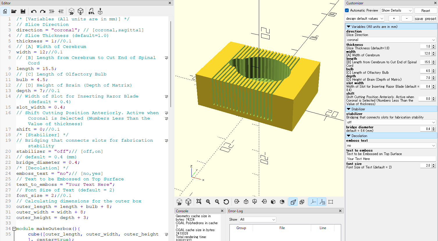
Review the 3D preview and, if necessary, return to the previous steps to adjust the parameters.
direction : Choose either "sagittal" or "coronal". The former should be selected when creating slices that section the sample sagittally, while the latter is chosen for slices that section the sample coronally.
font size : The font size for the embossing text can be set.
thickness : The value indicates the slice thickness. The default value is set at 1 (mm). To specify a slice thickness of 2mm, enter 2.
witdth, length, bulb and depth : Input values that are 10% larger than the measurements obtained in the previous step.
slot width : This item specifies the width of the slot for inserting a razor blade. Although the actual thickness of the razor is thinner, reducing the width of the slot excessively can make the fabrication process challenging.
shift : When "coronal" is selected and adjustment of the slice position is desired, the slots will shift anteriorly by the specified value of the shift setting. Enter a value that is less tha the value set for thickness.
stabilizer : Add thin rod-like structures that bridge the slots. These contribute to the fabrication stability of narrow slots.
bridge diameter : Define the diameter of the bridge structure as a stabilizer. If the default value of 0.4mm or a similar value is used, it can be easily cut with a razor blade.
emboss text : Choose either "no" or "yes". Upon selecting "yes," the designated text will be displayed at the top of the matrix.
text to emboss : Enter the text or numerical string. A long text will not fit within the designated space.
Push the Preview button on the top of the Editor pane. The outline of the matrix is updated based on the specified values. Review the 3D preview and, if necessary, return to the previous steps to adjust the parameters.

Obtain the STL file
Digital Fabrication
Load the STL file into slicer software compatible with the 3D printer. In the following steps, protocols will be provided for using the PreForm to fabricate the design with Formlabs' Form2 printer.
Run PreForm.
In the menu bar, click File > Open . The Open File window appears. Select the STL file and click OK.
Configure the orientation of the 3D model and the settings for support structures.
Select the printer model, material, and layer thickness.
Post-processing after fabrication
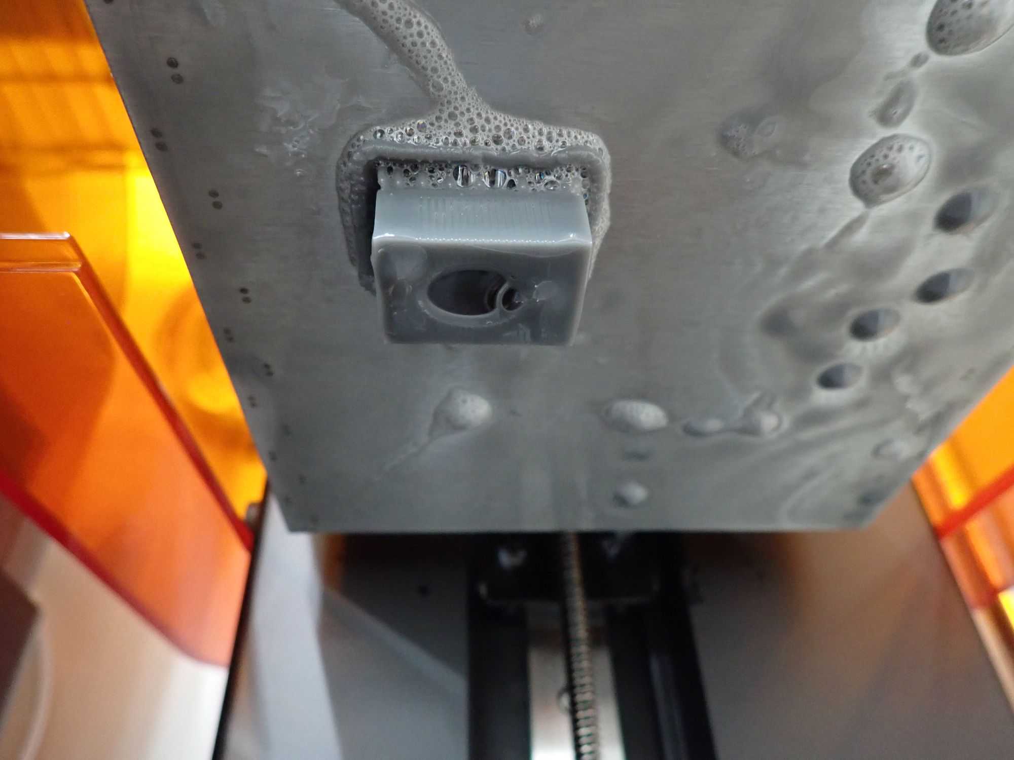
Remove the object from the build plate and either peel off the support material by hand or cut it off with diagonal cutting pliers.

Wash the object with isopropyl alcohol (IPA) for slightly longer than the recommended time for the resin used, in order to remove uncured resin from narrow slots. For more effective cleaning, the use of a magnetic stirrer or an ultrasonic cleaner is recommended.


